The three fundamental components of an RLC circuit are connected in parallel with one another and are therefore all subject to the same voltage in a parallel RLC circuit. However, the impedance of each branch determines its own current, which can be calculated using Ohm’s law.
Since the same voltage is applied to all three types of components in a parallel RLC circuit, the voltage is shared by all three types. However, there is a misalignment between the phases of the currents in the three separate paths. This means that there is no point in time when all three branches’ currents are at their maximum or zero.
As a result, the total current cannot be calculated by simply adding the currents in the resistor, inductor, and capacitor together.
Figuratively speaking, a parallel RLC circuit is depicted in Figure 1. Similar to series RLC circuits, understanding the total current and power consumption for the entire circuit or for each branch is essential.

In this circuit, each branch receives the same voltage supply. Therefore, to calculate the current flowing through each component, divide the voltage by the impedance of the branch. If that’s the case, we can combine the flows.
The currents in the three components must be added in vector form rather than algebraically because they are out of phase with one another (their maximum and minimum values are not simultaneously reached).
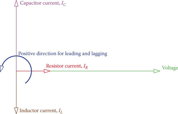
The three currents in a standard parallel RLC circuit are shown as vectors in Figure 1. This demonstrates that the resistor’s current is in phase with the applied voltage, while the capacitor’s current is ahead of the voltage (recall ICE), and the inductor’s current is behind the voltage (remember ELI).
In addition, remember that the voltage is the common variable for all branches, so the voltage vector is drawn first as the reference vector in this vector representation of the currents and voltage in a parallel RLC circuit. (In a series RLC circuit, this procedure began with the drawing of the current’s vector.)
The total current in a parallel RLC circuit is the vector sum of the currents in R, L, and C.
Currents in the inductor and capacitor are 180 degrees out of phase with one another, so when added together, their values cancel out. Thus, the formula relating the total circuit current I to the currents in its various parts (IR, IL, and IC) is

Parallel RLC Circuit Example 1
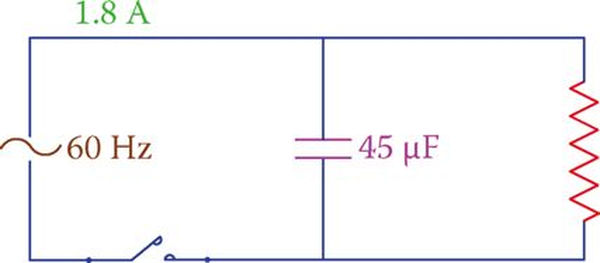
There is a 1.8 A current in the circuit depicted in Figure 3. Determine the applied voltage and the resistance of the resistor if the current through the capacitor is 1.5 A.
Solution
For 60 Hz frequency, the reactance of the capacitor is

Thus, the applied voltage is

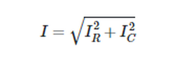
Because this circuit has no inductor, the value of L in Equation 1 is set to zero and the result is
Which leads to

And the resistance of the resistor is

If in Equation 1, the values for IR , IL and IC are replaced by  we have where I is the ratio of the applied voltage to the impedance Z of the circuit we are considering,
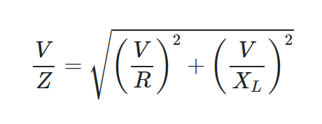
The connection between Z and R, L, and C is then as long as V is removed from both sides.

To calculate the equivalent impedance of the three components connected in parallel, use Equation 2. The circuit current can also be calculated by dividing the applied voltage by Z or by multiplying I/Z by the voltage directly.
Parallel RLC Circuit Example 2
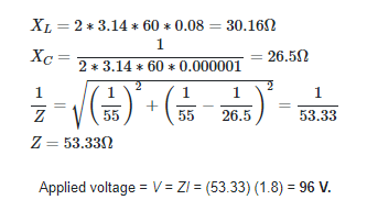
In the circuit shown in Figure 4, ![]() find the impedance of the circuit and the applied voltage.
find the impedance of the circuit and the applied voltage.

Solution
For parallel RLC circuits, the value of Z is implied to be less than R by Equation 2. Figure 5 depicts the three component powers and the apparent power as well as a vector representation of IR, IL, IC, and I.
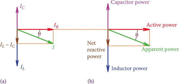
Simply adding the inductive and capacitive powers together in vector form yields the reactive power. The vectors for I and the apparent power S are either below or above the horizontal reference, indicating whether the inductive power (QL) or the capacitive power (QC) is greater. In the former case, the current precedes the voltage, while in the latter, the current follows the voltage.
Any circuit can be classified as leading or lagging because in practice most applications (including home and industrial circuits) are parallel circuits. The current in a circuit is said to be leading if it precedes the voltage, and lagging if it follows the voltage.
Power Factor in Parallel RLC Circuits
A lagging circuit is depicted in Figure 5. Most practical circuits are slow because of the presence of electric motors; this is true unless capacitors are added to the circuit, which introduce capacitive power to compensate for the effects of electric motors (see power factor correction). Parallel RLC circuit power factor =

It is important to remember that the power factor is not a complete circuit description. It requires the statement for ahead or behind to make sense. Power factor can be either leading or lagging in a circuit. Power is sometimes cited as the reason for who is in the lead and who is in the rear. A circuit with a leading power factor of 0.90, for instance, is considered to be highly efficient.
Parallel RLC Circuit Example 3
Current through the inductor is 100 mA, and the total current in the circuit shown in Figure 6 is 150 mA. Find the voltage that is being applied. Using the information that the frequency is 50 Hz, determine L’s value.
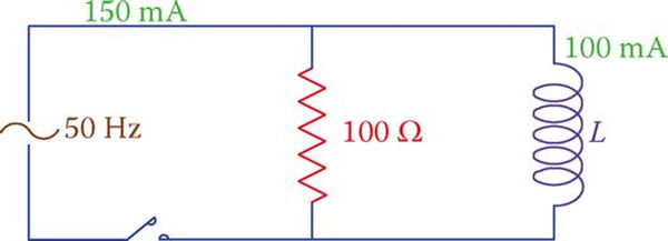
Solution
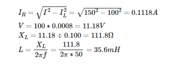
Multiplying the current through the resistor by 100 yields the applied voltage. Equation 1 reveals what happens when we reduce this circuit to just a resistor and an inductor.
If the current in a parallel AC circuit is greater than the voltage, the circuit is said to be in a leading position, and if the current is smaller than the voltage, the circuit is in a lagging position.