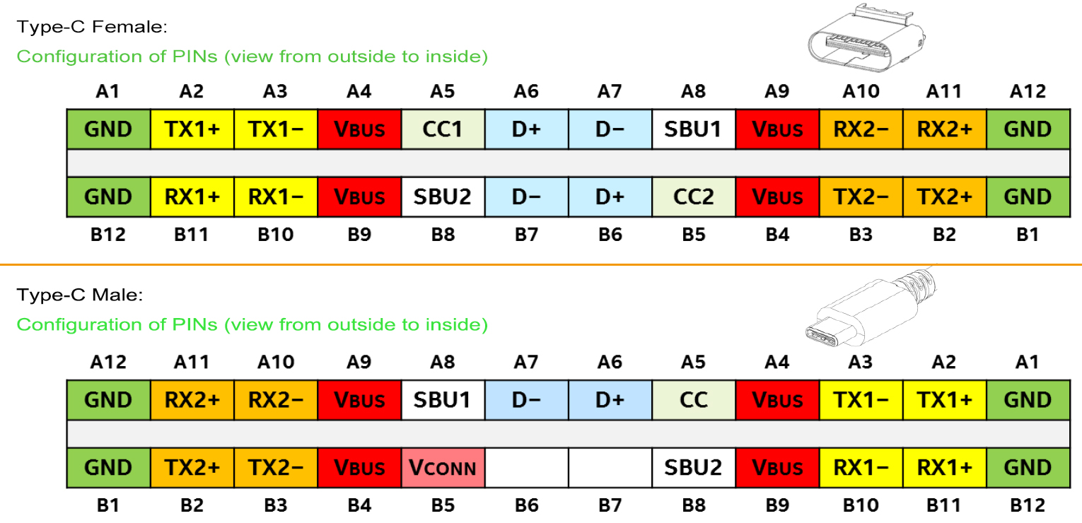
The USB Type-C connector is one variant. It is the only USB connector that works properly whether inserted in the front or back. It can be charged from a standard USB port, send and receive data, video, and audio, and output to a display.
In addition to being backwards-compatible with older standards, USB Type-C also has a unique dual-purpose design. To determine whether one end of a USB Type-C cable is a host or a peripheral, devices on either end must communicate with one another. It is important to note that data and power roles must be communicated independently after the cable has been connected.


Downstream Facing Port (DFP) refers to the host computer’s data port, while Upstream Facing Port (UFP) is the name given to the device’s peripheral connection (UFP). The end that produces energy is known as the source end (Source) and the end that consumes energy is known as the sink end (Sink) (Sink).
Some gadgets can switch between data and power functions simultaneously, a feature known as “Dual Roles of Data” (DRD). As data is transferred between the two gadgets over the Type-C “Configuration Channel Pin CC,” the CC wire specifies which gadget will act as the power source.
How is a USB-C to USB-C cable connected?
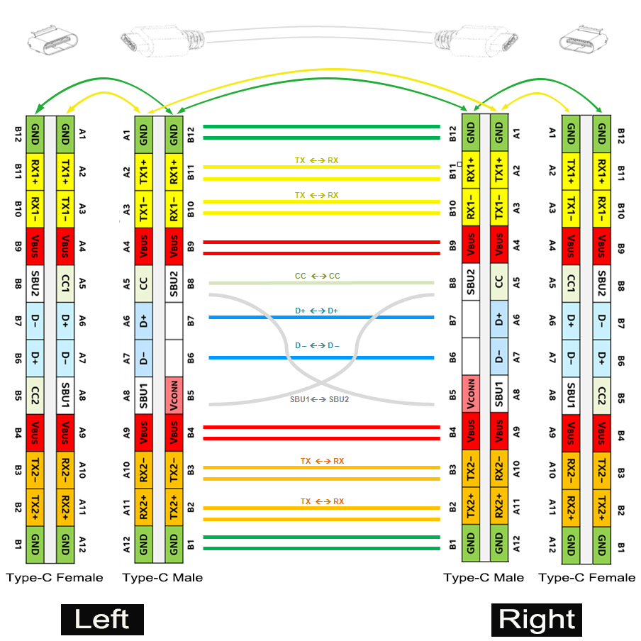
Here is P-Shine Electronic Tech Ltd.’s provided wiring diagram for their high-quality USB-C to USB-C GEN 2 Cable.
Connection Status 1: Direct and unflipped

The above illustration depicts the connection in its Unflipped state. The RX1 pair is connected to the RX1 pair, the RX2 pair is connected to the RX2 pair, the D+ is connected to the D+, the D- is connected to the D-, the SBU1 and SBU2 are connected, and the CC1 and CC2 are connected, respectively.
There are situations in which VCONNs on either end of a cable are superfluous (B5 to B5). Electronic mark (E-mark) chips require a connection between pins 5 (B5) on the left and right plugs of the USB-C connector on the PCB before they can be installed.
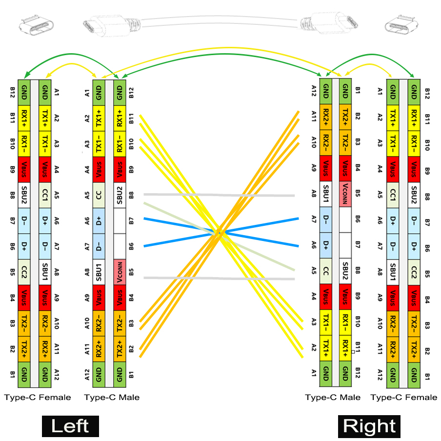
Transposition to the second state

Since USB-C permits front and back insertion, the USB-C connection is flipped when the left plug and socket remain the same and the right plug and socket switch places.
The RX1 pair is linked to the TX2 pair, the RX2 pair is linked to the TX1 pair, D+ is still linked to D+, D- is still linked to D-, SBU1 Connects to SBU1, SBU2 Connects to SBU2, and CC1 is linked to CC2 via the CC wire, moving from the left-hand socket to the right-hand socket. As such, information travels quickly from the left (via RX1+/- and TX1+/-) to the right (via TX2+/- and RX2+/-).
It is possible to switch the positions of the left and right plugs. Direct (equivalent to flipping both ends at once) and one-sided flipped connections make it appear as though there are four distinct ways to make a connection.
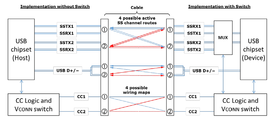
Thus, in a USB-C to USB-C 3.1 cable, you will see four pairs of high-speed signal pairs, but only two will be active at any given time; however, when you flip the plug to the other side, the two idle signal pairs will take their place. Alternating between host and peripheral power supply or data transfer roles causes constant toggling of signal pairs.
To ensure proper communication in the USB 3.1 system, a multiplexer is used to set up the RX/TX data pairs for each of the different connection states. Below is a diagram depicting the various paths that data pairs could take from one USB Type-C port to another. Once the plug and socket orientation has been determined by checking the CC1/CC2 status of each terminal, the CC logic controller can finish configuring the multiplexer’s routing functionality within the multiplexer or the USB chipset.
