Schematic diagrams in the electrical trade are extremely helpful in conveying information to the repairman. Size, shape, and identification number of components, as well as their placement in relation to one another and the rest of the circuit, are all shown.
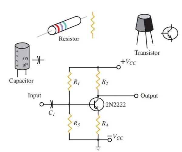
You can use a diagram for anything from setting up the circuit to explaining how it works to figuring out why something isn’t working. The parts of a circuit are represented by symbols. Commonly, lines represent wires or conductors on diagrams. There are a number of ways to demonstrate their interconnectedness. Refer to Figure 1.

What is Schematic Diagram
A schematic diagram is a common form of electrical drawing. View Figure 2. As schematic diagrams go, this one is fairly standard. The diagram lays out the necessary components and how they fit together. The apparent separation does not correspond to the real-world distances between the parts.
The schematic diagram’s primary function is to display the connections between the parts. Components connected in series or in parallel are denoted on the diagrams. Schematics can help you solve problems much faster.

Trouble in a circuit can be located with the help of meters, wiring diagrams, schematics, and knowledge of electronic theory. Schematics and the application of electronic theory are necessary for troubleshooting many circuits.
What is Elementary Line Diagram & Wiring Diagram
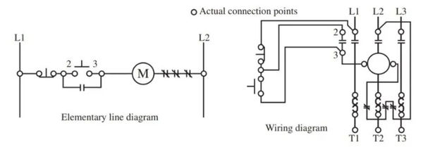
In Figure 3, we can see the similarities between a simple line diagram and a circuit schematic. A standard motor control system, as depicted here, employs a stop-start mechanism.
On the left, we see a simplified line drawing that resembles a schematic. Its primary application is in the manufacturing sector, where it is used to depict the interconnectedness of various electrical controls.
This is the actual wiring diagram on the right. With this, the control system could be linked together.
The wiring diagram shows where all the physical connections and components would be located in the finished product, while the simplified diagram shows how the circuit works and what parts go where. There is a specific function for each type of diagram.

The elementary line diagram is used to clearly express how the circuit works. The wiring diagram is used to install the system.
An entire system’s functionality can sometimes be depicted using a block diagram. See Figure 4 for a schematic representation of the internal workings of a common AM radio. The amplifier and other parts are arranged in stages.

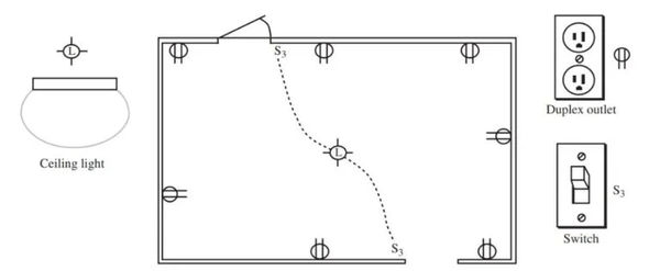
A typical diagram for wiring a single room in a house is shown in Figure 5. The diagram essentially pinpoints where things like lights, outlets, and switches are situated.
Because the electrician is expected to be familiar with electrical codes pertaining to wire sizes, switch amperages, and breaker sizes, this information is not included on the plan.

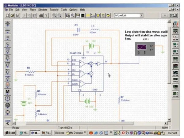
Using a circuit design program can be helpful when putting together an electrical system. These days, electronic circuit design is almost exclusively a computer- and software-based process. View Figure 6.
Components can be chosen from menus and dropped onto the drawing board in these applications. For each part, you can specify its electronic characteristics like resistance, current, and voltage.

Electronic circuits can be not only drawn out using software systems, but also simulated in the same way as if they were built using physical electronic components.
The flexibility of virtual meters allows for connection at various points in the circuit, facilitating experimentation and testing. The circuit layout can be used to generate a comprehensive bill of materials.
A printed circuit board’s pattern can be printed. Because of this, designing and testing the circuit takes much less time than if it were constructed with real components. After the circuit layout has been thoroughly tested, it can be constructed using physical parts.