North America’s electrical grid is a system of interconnected generators, transmission lines, substations, and consumer devices that move electricity from its source to its destination.
The electrical grid is defined as an interconnected network of power stations, transmission lines, and distribution stations that transmit electrical power from suppliers to consumers. It provides a point of connection for renewable energy systems that produce electrical power.
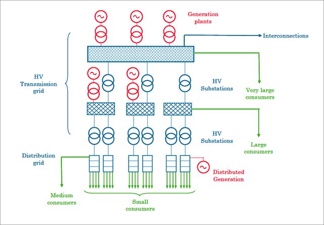
Transmission is the process of moving electricity over long distances; the transmission system transfers power in large quantities between transmission substations at power plants and renewable energy systems and distribution substations.
An electrical substation is a network of switching equipment, control equipment, and transformers that are used to convert the voltage to a different level. Substations form the basic interface to the transmission system.
The term “distribution system” refers to the network that carries electricity from the distribution substation to the end user.
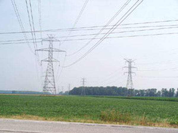
High-voltage transmission lines may need to be doubled when more powerful renewable energy systems are added to the grid.
This is because it is more efficient to run the new high-voltage transmission lines in parallel with the existing ones, and the transmission company owns the land in between.
Control of the Grid
The grid receives and distributes electricity generated at conventional power plants as well as those using renewable energy sources.
With the help of the grid control system, electricity can be routed from one part of the grid to another as needed, and problems can be isolated to a specific part of the grid.
If there is an issue with one of the three major grid sectors in the United States, it will not spread to the other two.
Sector and subsector control centers constantly monitor the grid to ensure adequate power is available and that any outages are contained to a small area.
Advanced computer and network controls have been added to grid switching equipment in recent years, allowing for more streamlined operations.
Industrial and commercial users are installing this technology in their substations so that grid controllers can identify which loads can be safely shut off in the event of a gridwide outage.
With the help of these more advanced control systems, load sharing is possible, allowing grid control companies to redistribute power as demand fluctuates throughout the day.
All of these controls are being integrated into something that is now being called the smart grid.
Smart grid refers to the electrical distribution technology that uses computer-based remote control and automation to increase the efficiency of electricity delivery and provide information to the customer in order to optimize electrical power use, though there is some disagreement as to the precise definition of the term.
Electrical Power Transmission System
The modern electrical grid can trace its origins back to the earliest days of electricity production. Getting electricity from generators to users in a timely manner was a major challenge for the industry’s pioneers.
Since the demand for electricity from faraway places fluctuated over time, it was necessary to link together multiple power plants so that their combined output would always be available.
A related problem was how to keep consumers’ lights on when power plants had to be taken offline temporarily for maintenance or other reasons.
To regulate the flow of electricity through the transmission lines and to maintain the increasingly complex generation and distribution system, cooperation between producers was required.
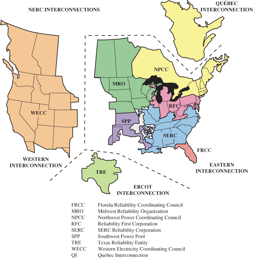
The interconnections maintained by NERC are depicted in Figure 2 below.
In the map, the four major interconnections are labeled as Quebec, Eastern, ERCOT (Electric Reliability Council of Texas), and Western.
The legend at the map’s base details the individual nodes that make up each connection. Large swaths of Canada are connected by each of the three interconnections in the country: Quebec, Eastern, and Western.
Almost always, a three-phase transformer is used to boost the voltage from different generators for transmission, and subsequent substations near the customer reduce the voltage to the appropriate level.
The voltages used for the transmission system are separated into different voltage levels for long-distance transmission. In North America, one of the highest voltages used is 765,000 V. Other lines transmit voltage at 500,000 V, 345,000 V, and 230,000 V.
In order to transmit data more efficiently over greater distances, higher voltages are typically employed. The three-phase voltage for large commercial and industrial customers is typically supplied at high voltages, and the customer supplies the transformers to reduce the voltage to the final value.
The electrical power company “steps down” the three-phase current to single-phase for homes and smaller businesses. Some parts of the world (specifically some parts of Europe) provide three-phase power to residential buildings.
From the power plants, through the green transmission lines, and finally to the homes and businesses, the entire process is depicted in Figure 3. (red).

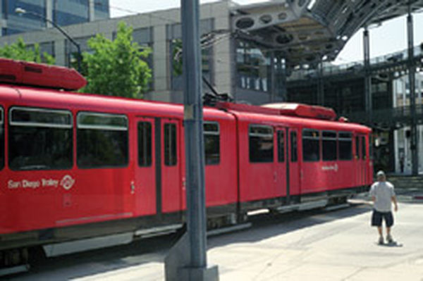
Electric trolleys in larger cities were one of the earliest applications of electricity and a grid. (The photo depicts a functioning electric trolley in present-day San Diego, California.)
When electricity was first generated, transmitted, and distributed, both direct current and alternating current were transmitted via separate wires.
Power was distributed to customers who needed dc on one set of lines and to those who needed ac on another set.
Companies known as transmission companies (transcos) own and operate the physical transmission infrastructure, including the lines, towers, transformers, and switchgear.
Companies that manage the grid function, or the interconnection and routing of electricity through the electrical system, are known as grid companies (gridcos). There may be local or regional utility companies that manage certain aspects of the grid.
Electricity is frequently traded between different parties under both short- and long-term contracts, making it akin to a commodity. The sale of electricity and the ownership of certain types of equipment are subject to laws and regulations.
Electrical Power Distribution
Distribution is the last step in the process of delivering power to the customer.
A distribution substation is a large set of transformers and switching equipment that is located at the edge of a city or near an industrial site that steps down the voltage from the transmission site to a lower voltage for distribution.
The lower voltage is transmitted to the customer’s location via feeder lines, which may be either overhead or buried.
The transformers in the service systems that are geographically close to the end users are responsible for reducing the voltage to the delivered level and providing the service drop.
Finally, the wiring at the end user’s location and the connection to the earth ground constitute the final part of the grid.
Grounding System
The grounding system for electrical power systems is the earthing system used as a safety measure to ensure that certain parts of a system are at the same electrical potential as the earth’s surface.
The standard grounding system includes one or more copper rods driven into the ground to a depth of 2.4 meters (8 ft).
Parts of the system, like metal cabinets, are kept at ground potential by bonding or connecting them with heavy copper conductors to these copper rods.
In the case where multiple rods are needed, the potential of each rod can be maintained by connecting them with a copper conductor.
There are two applications for the ground network.
By properly grounding the frame, workers are protected from electrical shock in the event that the frame becomes “hot” due to damage or a system failure.
Any metal in the system frame can make contact with the ground rods, creating a low-resistance electrical path to the earth that will draw a lot of current and trip a circuit breaker.
It is possible that a person could be electrocuted or severely shocked if they touched any metal component of the system while it was not grounded and the circuit breaker did not trip.
If you find a circuit breaker that has tripped open, you must check to see if a short circuit has occurred before resetting it.
If the circuit breaker is closed and then immediately opens again, troubleshooting is required to determine the source of the short circuit.
Second, grounding a system helps prevent damage from occurring in the event of a fault or lightning strike.
In the event that a renewable energy system is struck by lightning, the electrical energy contained within the bolt must be quickly dissipated into the earth.
If the electrical system or its structures are not grounded properly, the location where the lightning strike enters the system can be severely damaged.
It is important to check the grounding system on a regular basis to make sure that all connections have a low resistance path to the earth.
To further safeguard the system in certain installations, additional lightning arrestors may be required.
The electrical code mandates the installation of a grounding system, and furthermore, calls for its annual inspection and maintenance.
Ground Fault Interrupt Circuit Breakers
Ground fault interrupt (GFI) circuit breakers are an essential safety feature (for example, preventing workers from receiving fatal electrical shocks in damp environments).
When a person is receiving an electric shock, the difference between the hot and neutral currents can quickly grow to dangerous levels, causing this special circuit breaker to trip.
A portion of the hot and neutral lines are enclosed within a small current transformer, which functions as the circuit breaker.
When the current in each line is equal, the core is not affected by any of the fluxes. When there is a discrepancy, a special circuit is triggered to shut down the power supply. When working on a rooftop or other wet area of a renewable energy system, this is an essential feature.
The GFI breaker will trip if there is a difference between the hot and neutral lines, as this indicates an electrical shock has occurred and the current is returning to ground rather than going through neutral. An electric shock is still possible, but it won’t last long and won’t be as dangerous.
Flashover
When two or more high-voltage lines touch, or if one of these lines contacts a lower-voltage feeder line or grounded metal parts, a catastrophic failure can occur. During a storm, either scenario is possible (a tree falling across lines, for example).
When high voltage is applied to low voltage systems, a phenomenon known as flashover can occur.
A flashover poses a significant risk, as it can lead to a fire or other catastrophic event. The majority of the current will flow through the neutral line to ground if it is properly grounded, which can trip breakers and prevent more serious consequences.
Electrical Power Utilization
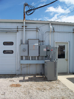
Electrical power is routed to the customer either on overhead or underground wiring. Figure 5 shows an overhead connection with all of the switchgear and metering.
Transmission lines for electricity have a small margin for error, so a temporary overload won’t fry the circuits, but they’re vulnerable to damage from severe weather.
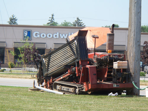
A specialized machine (see Figure 6) that installs a conduit underground without digging a trench can be used to bring power underground. As it drills horizontally about 3 feet below the surface, it installs segments of pipe.
As the drill and pipe are retracted one segment at a time, they draw the plastic electrical conduit into the hole they’ve made. Electrical cable can be pulled through the conduit thanks to an internal pull wire.
In crowded areas or in places where unsightly wiring is not desired, underground wiring is used despite its higher installation cost. The backup circuitry is typically set up in the event of a malfunction.