An electric motor cannot function properly or reliably without some sort of control mechanism. There is a wide spectrum of complexity in motor control circuits.
Manual controls (manual starters, drum switches), magnetic controls (magnetic starters), motor drives, and programmable logic controllers (PLCs) can all be used in reversing motor control circuits in the same ways that they can be used in non-reversing motor control circuits.
There are numerous options for connecting a motor to a control circuit. Each of these techniques can be used independently or in tandem to manage how a motor functions. There are benefits and drawbacks to using various wiring techniques for motor control.
Direct hardwiring, hardwiring with terminal strips, PLC wiring, and electric motor drive wiring are the four fundamental approaches to motor control wiring.
Direct Hardwiring
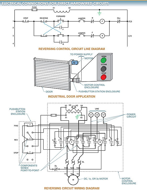
Direct hardwiring is the oldest and most straightforward motor control wiring method used. In direct hardwiring, the power circuit and the control circuit are wired point-to-point. See Figure 1.
In point-to-point wiring, each component is hardwired (connected) to the next component in the circuit in direct sequence, as shown in the schematics. Overload (OL) contact is connected back to the transformer X2 terminal after being connected to the fuse, stop pushbutton, reverse pushbutton, forward pushbutton, and so on.
For a while, a hardwired circuit may function normally. Direct hardwired circuits have the drawback of being time-consuming to troubleshoot and modify.
To diagnose a problem in a direct hardwired circuit, for instance, one must learn about the circuit’s operation, take relevant measurements, and locate the source of the issue. It is possible to learn how a circuit works by looking at its wiring diagram.
It is possible to figure out how a circuit is wired even without a diagram by following each wire as it moves from one component to another. However, it takes time to trace each wire in a circuit until you find the one that has a problem and solve the circuit’s problem.
Working on a circuit multiple times and learning its operation and components allows you to save time in the long run.

Modifying a direct hardwired circuit can be challenging. It is necessary, for instance, to locate the precise connection points for a pair of indicator lamps—one for forward and one for reverse—that will be added to a motor control circuit. The lamps can be wired into the control enclosure once the precise connection points have been identified. There may still be issues with making the connection, even if the exact connection points have been identified (such as there not being enough room under the terminal screw, etc.).
Adding new wires to an existing circuit may be all that’s needed to make some changes, such as installing additional indicator lights (both forward and reverse). To make these adjustments, it is not necessary to relocate or remove any existing wiring.
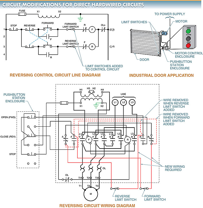
Adding limit switches or other complex components to a circuit is one example of a more involved modification. Adding forward and reverse limit switches to a circuit, for instance, necessitates modifying the existing wiring and/or installing new wiring. For example, see the diagram in Figure 2.
It is necessary to remove (or open) the wires connecting the NC interlock contacts of the forward and reverse coils to the pushbuttons before adding the limit switches to this circuit. To know which wires to open and where to find the limit switches, the technician making the circuit modification must have a wiring diagram of the circuit (or understand the circuit from past experience).

Hardwiring Using Terminal Strips
Hardwiring to a terminal strip allows for easy circuit modification and simplifies circuit troubleshooting.
When using a terminal strip to wire a control circuit, it is helpful to label each wire with a reference point on the line diagram so that you can tell which wires go to which components. A wire reference number is assigned to each point of reference. To see this, please refer to Figure 3. Numbering systems for wires typically went from left to right.
However, in most modern illustrations, the left power line is labeled “1” (L1 or X1) and the right power line is labeled “2” (L2 or X2). By doing so, terminal 1 and terminal 2 will always have the voltage from the control circuit. This is helpful for a technician who is trying to figure out what’s wrong with a circuit. If more than one connection to a specific terminal is needed, simply add a jumper to the terminal strip.

Troubleshooting the Motor Circuit
The technician can bypass the rest of the circuit and go straight to the terminal strip to take measurements and narrow down the source of the problem. First, the DMM is connected to pins 1 and 2 of the board. The primary side of the transformer is at fault if the voltage is off at that point. If the voltage is correct at both terminals, you can narrow down the problem by leaving one DMM lead on terminal 2 and testing the others.
The numbered terminal strip and associated wires not only facilitate circuit modification, but also troubleshooting. This is due to the fact that switching requires disconnection and reconnection of virtually all wires at the terminal strip. The evidence can be found in Figure 4.
