Single-phase (1) and three-phase (3) AC generators are the two primary categories. Both single-phase and three-phase AC generators function in the same way, but the armature count is different. Three-phase generators, as opposed to single-phase ones, produce a more stable voltage. There are two common ways to connect three-phase alternating current generators: wye and delta.
Single-Phase AC Generator
In a single-phase (one-wire) ac generator, one cycle of ac is generated for every full rotation of the armature. Refer to Figure 1.
Since the armature is not yet cutting across any magnetic lines of force at position A (0° of rotation), there is no voltage and no current in the external (load) circuit.
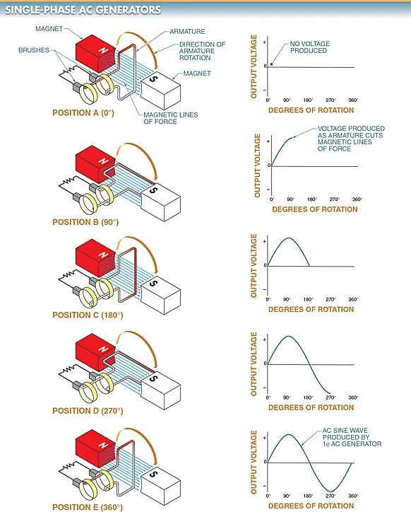
In order to generate current in the external circuit, the armature must rotate from position A to position B, where each half of the armature cuts across the magnetic lines of force. The current only grows from zero to its maximum in one direction. The first 90 degrees of a sine wave depicts the value of the current as it varies.
Even as the armature transitions from position B to C, the flow of current remains constant in the same direction. From its peak, the current gradually drains to zero. The second quarter of a sine wave, from 91 degrees to 180 degrees, represents this varying current value.
Each half of the coil cuts across the magnetic lines of force in the opposite direction as the armature continues to rotate to position D. The flow of the current is altered as a result. At this instant, the current is at its most negative point, having started at zero. Third quarter of the sine wave (181° to 270° of rotation) depicts this varying current value.
Eventually, the current will be zero as the armature completes its rotation and reaches position E (or position A again). The sine wave has now completed a full 360 degrees.
Three-Phase AC Generator
Three-phase (3) AC generators work in the same way as single-phase (1) AC generators, with the exception that the armature windings are staggered by 120 degrees. Refer to Figure 2. A 3 phase alternating current generator will produce three voltages that are 120 degrees out of phase with one another.
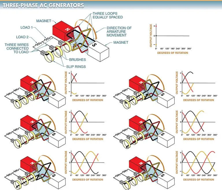
The armature coils of a three-phase alternating current generator connect to six wires. In order to simplify the process of connecting the generator to the load, these cables are joined together before being brought out.
Both a wye (Y) and a delta (∆) connection can be used to link armature coils together. The AC generator’s output electrical characteristics are set by how the leads are connected. Notice in particular Figure 3.
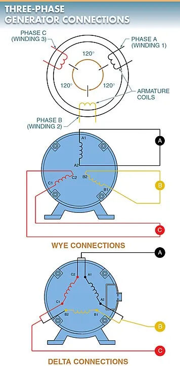
Joints that branch off in two different directions, or “Y” connections. For a wye (Y) connection, only one end of each coil is joined together, while the other ends are left free for use with other devices. Connecting the phase-ends A2, B2, and C2 of this circuit will make it easier to work with. Please refer to Figure 4.
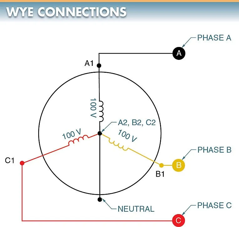
Given that there is zero voltage across the neutral point, the three ends can be connected without risk. When phase A is at its peak, phases B and C work in reverse. When the vector sum of B and C’s opposite values is performed, the resulting force is exactly equal to A. Refer to Figure 5.
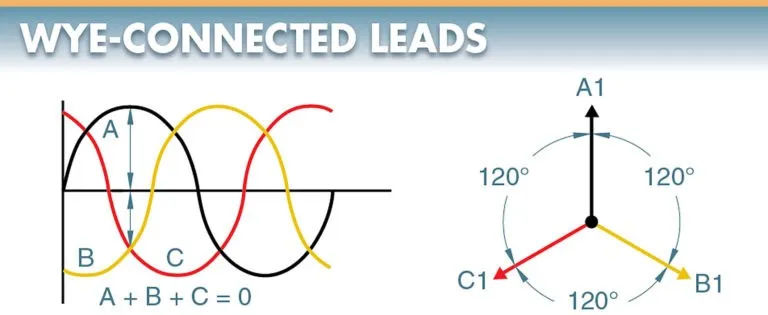
As a result, there is a significant pressure difference (voltage) between the terminals of coils A1, B1, and C1, but none between terminals A2, B2, and C2. The generator’s common wire (lead) may or may not be connected. It is the neutral if it is connected.
The neutral wire, or common wire, is not connected to anything outside of the generator in this simplified diagram of a wye-connected generator. Each load is connected across two phases in series in this setup. An AC generator with a wye connection has a voltage between any two lines equal to 1.73 (3) times the voltage of any one of the three phases. The voltage between any two lines in a wye configuration will be 173 V (100 1.73) if the 1 voltage is 100 V. The same amount of current flows through both coils because they are connected in series.
The vector representation of an AC generator’s output voltage provides yet another analytical lens through which to examine this quantity. The magnitude and direction can be represented by a vector. To visualize a vector, imagine an arrow pointing in a particular direction, with the length of the arrow corresponding to the magnitude (voltage or current) in that direction. A look at Figure 6 would be helpful.
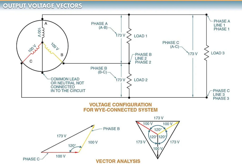
Phase voltage is the voltage measured across a single winding. As the name implies, line voltage is the voltage that is measured directly between the lines. Phase A, Phase 1, and Line 1 are all synonymous in discussions of electrical diagrams.
All three phases of a wye-connected AC generator can power a light. Each phase contributes to the illumination of every light by delivering the one watt of power generated. All three wires, A2, B2, and C2, travel back to the generator as one.
A wye-connected three-way lighting circuit is considered balanced if the three loads have the same power requirements. The neutral wire in a balanced circuit does not conduct electricity because the total current in the circuit is zero.
Large-scale electrical distribution networks are always conceived as 3-phase systems, with loads spread out evenly across the phases. Unbalanced current is the only type of current that travels along the neutral wire. Due to the relative ease with which most systems can be maintained in equilibrium, this is typically kept to a minimum. As a rule, the neutral wire is linked to the ground.
Phase-to-neutral voltage (one-phase low voltage), phase-to-phase voltage (one-phase high voltage), and phase-to-phase-to-phase voltage (three-phase voltage) can all be attained via a wye connection. 7th Figure Line voltage is another name for phase-to-phase voltage.
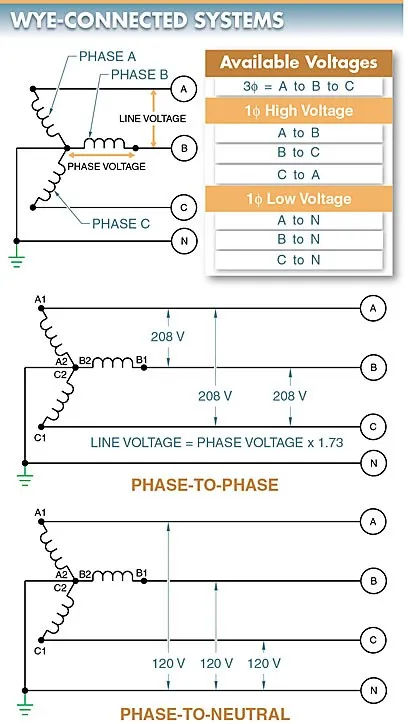
With a 3 phase wye connection, the voltage across the neutral conductor is the same as the voltage produced by each individual coil. In the case of a generator putting out 120 V between A1 and A2, that voltage is also present between B1 and B2 and C1 and C2. The voltage from each coil’s output appears between the phases and the neutral in a 3 wye-connected system.
For example, in a high-voltage, wye-connected AC generator like those found in power plants, a phase-to-neutral voltage of 2400 V results in a phase-to-phase voltage of 4152 V, and a phase-to-neutral voltage of 7200 V results in a phase-to-phase voltage of 12,456 V.
Wye-connected systems allow utilities to reduce transmission losses while transmitting at higher phase-to-phase voltages, which is useful because many generators are only rated to produce 2400 V or 7200 V per coil. This is because power loss decreases as the transmitted voltage increases.
Power, denoted by the formula P = E I, is defined as the product of voltage times current. To produce the same amount of power, a higher voltage requires a smaller current.
The relationship between power (or power loss) and current squared times resistance is expressed by the equation P = I2 R. For a given resistance in a power line, the power loss decreases as the current decreases. For this reason, higher voltages allow power lines to transport more energy than lower ones. Long power lines in rural areas benefit greatly from efforts to reduce power loss along the length of the wires carrying the electricity.
Links in the Delta () Structure. Each coil’s terminals are joined together to form a continuous loop; this configuration is known as a delta () connection. The delta connection is another option for connecting the coil windings of a three-phase alternator. Figure 8 is shown below. The windings on the coils are 120 degrees apart, just like a wye connection.
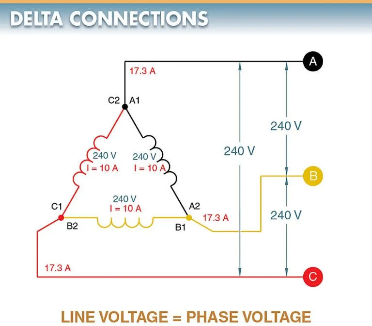
The voltage between any two lines in a delta-connected system is always the same as the voltage produced by the coil winding. This is due to the fact that voltage is typically measured right across the coil. If the voltage between any two lines is the same as the voltage generated by the coil, then the voltage between the lines is also 240 V. Line voltage and phase voltage cancel each other out in a delta configuration.
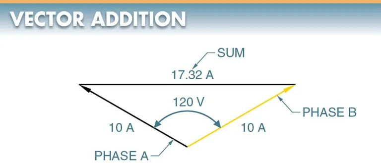
If you trace the current back along any line in a delta-connected system, you’ll find that it originates from a pair of coils. The origin of phase A lies in the A1, C2 nexus. The coils are 120 degrees apart, just like in a wye-connected system. Because of this, the line current is the vector sum of the currents in the two coils.
Equal phase currents characterize a balanced system. The line current is 1.73 times the current in one of the coils in a balanced 3 delta-connected system.
If we take a delta-connected system as an example, we might assume that each phase winding is carrying 10 A. However, the current in each line is 17.32 A. This variation in amperage is due to the fact that in a 3 circuit, current flows through each winding at a different instant in time. Occasionally, only two lines will have current flowing between them. In other cases, two lines will act as a source for the third line to receive current.
There are always multiple paths for current to take in a delta connection, making it functionally equivalent to a parallel connection. This vector addition is required because the currents are 120 degrees out of phase with each other. For more information, please refer to Figure 9.
One power line may be grounded in older delta-connected systems, creating a grounded corner. Because of the potential for danger they present if misunderstood, corner-grounded delta-connected systems are no longer in use. Voltage readings on a digital multimeter (DMM) set to measure voltage should be consistent across all phases when testing to ground. If not, either power is being cut to one leg of the system or it is a corner-grounded delta-connected system.