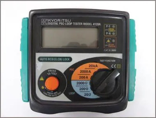
Methods of measuring resistance, such as the Volt-Ammeter Test, the Wheatstone Bridge, the Insulation Tester Powered by a Generator or Batteries, the Bridge Megger, and the Fault Loop Impedance Tester, are discussed, along with circuit diagrams for each.
Resistance values can be measured with the help of parallel and series ohmmeter circuits. However, there is a threshold beyond which the reliability of both circuits begins to degrade.
For low resistance values, parallel ohmmeter circuits perform better than series circuits, but errors can creep in as resistance values get still lower. Terminal resistance and lead resistance, both of which are introduced when connecting the test resistor, become noticeable.
The series ohmmeter circuit is superior to the parallel circuit for higher resistance values; however, as the resistance value increases, the current through the resistor and meter decreases. The meter reaches an inflection point when it can no longer provide a reliable reading.
Volt-Ammeter Testing
If you pass current through the resistor and measure the voltage across it at the same time, you will have a reading that is accurate enough for most applications. Ohm’s law is then used to determine the resistance.
To improve precision, the circuit’s connections should be carefully made. Two possible circuits are depicted in Figure 1.

Both the voltmeter and the resistor in Figure 1(a) will be measured by the ammeter. If the resistor’s resistance is small in relation to the voltmeter’s resistance, the difference in amperage reading can be disregarded. For instance, if the ammeter is reading 1 A and the voltmeter is reading 50 μA, the ammeter will not be able to distinguish between the two values.
Conversely, if the current through the resistor is 100 μA, a suitable ammeter would read a current flow of 150 μA (IR + Im), resulting in a significant percentage of error. Therefore, the circuit shown in Figure 1(a) is superior for determining extremely small resistances.
A voltmeter, as shown in Figure 1(b), is connected across the power source. Current only through the resistor is now being measured by the ammeter. In this circuit, V = Vm + VR is the reading on the voltmeter, which is the same as the supply voltage or the voltage drop across the resistor and ammeter in series.
To get a reliable reading from this circuit, the voltage across the resistor must be significantly higher than the voltage drop across the ammeter. A voltage drop across an ammeter of 50 μA movement and 5 k internal resistance would equal V = IR = 50 μA x 5000 = 0.25 V.
The PD across the resistor needs to be significantly higher, preferably 60 V or more, for optimal performance. The error grows more severe at lower voltage levels.
These techniques for determining resistance are extremely restricted in terms of precision and adaptability. With the use of two meters, the potential for making mistakes is amplified. It is also necessary to modify the voltage and current to meet the specifications of the measuring devices (resistors and ammeters).
If an excellent quality analogue multimeter with a high internal impedance is used, the circuit depicted in Figure 1(a) should be adequate. Low circuit loading is achieved by using an analog multimeter with an input impedance of 10 MΩ or higher. However, a high-quality digital multimeter can stand in, provided it provides the same level of precision.
Wheatstone Bridge
Since its initial description by S. H. Christie in 1833, the Wheatstone bridge circuit has undergone many improvements. Not until (Sir) Charles Wheatstone in 1843 did anyone pay any attention to it.
Its original purpose was for precise measurement of resistance values, but it has since been repurposed for use in a wide variety of circuits. The original circuit is shown in Figure 2(a). Included in its construction are three known resistors and an unknown resistor serving as the bridge’s fourth arm.
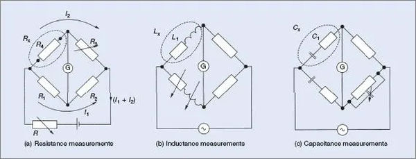
Alterations for measuring inductance (Figure 2(b)) and capacitance (Figure 2(c)) are shown. Many variations on these three circuits exist, and they are typically given the names of the people who first came up with them. It’s the original bridge circuit that serves as the basis for all the variations.
With good quality equipment the bridge circuit will measure accurately down to 0.01 Ω. The standard bridge circuit’s minimum requirements are approximately met here. By making a few tweaks to the original circuit, the bridge can be used to take precise readings down to 0.001 Ω.
Resistances with vastly different values can be measured by adjusting the resistance ratio between R1 and R2 in the bridge’s arms. When the meter pointer is held steady at zero, regardless of the voltage used to supply the bridge, the circuit is properly adjusted. Once this condition is met, we say that the bridge is balanced.
It’s important to note that whether the voltage is high or low, the corresponding current through the bridge will be high or low, leaving the meter vulnerable to overload and damage in its unbalanced state. In most cases, a sensitive moving-coil meter with a center-zero scale will be used as the meter in the circuit. In other contexts, it’s called a galvanometer.
The voltage drop across Rx in Figure 2(a) is equal to the voltage drop across R1 when the bridge is in equilibrium. Also, the potentials across resistors R2 and R3 are equivalent because of this:
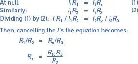
In actuality, the ratio between the two resistance arms, R1 and R2, is typically a tunable 0.1, 1, 10, 100, or 1000. Using this method, the range of the bridge circuit can be increased to accommodate a greater variety of input values.
This entails that multiplicative factors may need to be considered when calculating resistance values obtained via the bridge.
Wheatstone bridges are useful, but the values of R1 and R2 are not always known in practice. It is common practice to label them as a switch, with the position of the switch indicating the ratio. The values of the variable resistor R3 are used as-is to determine Rx. In this case, the value obtained by R3 in the null position is multiplied or divided by the given ratio.
The calculations needed to use a bridge circuit are shown in the next two examples.
Example 1
One side of a bridge has a resistance of 10 kΩ, the other of 1 kΩ, and the third of 3.95 kΩ. Determine the measured value of the resistance.

Example 2
The resistances on a bridge read R1 = 100 Ω, R2 = 1000 Ω, and R3 = 68.4 Ω. Find the value of the resistance being measured.

Insulation Resistance
A battery-operated circuit similar to that shown in Example 2 is not practical, accurate, or convenient for measuring very high values of resistance.
It is essential that the circuit under test can sustain a high voltage in order to allow a sufficient current to flow. This is essential for a meter to provide an accurate reading.
The minimum test voltages required by Australian Standards must be adhered to. It’s roughly twice the voltage required to run the circuit. As an example, the required test voltage is 500 V on a 240 V circuit. The recommended voltage for testing between phases is 1000 V.
Meggar Instruments Ltd., a modern-day English company, was likely the first to produce a device for such examinations. Evershed and Vignoles was the original company name, and “Meggar” was the unit’s trade name. The trademark is now commonly used as a synonym for the type of instruments it describes. There are other companies that make similar test equipment, and they should all be called insulation testers.
Both a hand-cranked generator and dry cells and an electronic circuit can be used to produce the required voltages.
Generator-Powered Insulation Testers
An internal power supply is required if the instrument is to be considered truly portable. In the first meggar, this was accomplished by cranking a generator. Earlier models relied on a direct current (DC) generator, while more recent ones use the powerful modern magnets rotating inside a coil to generate an alternating current. The instrument’s internal circuitry converted the resulting alternating current (AC) to direct current (DC). Figure 3 depicts the circuit of a DC generator and insulation tester.
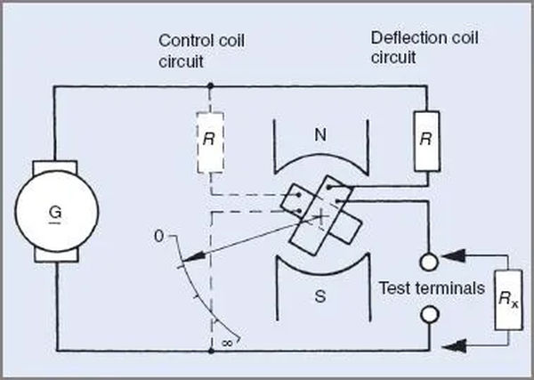
Since the generator, deflecting coil, deflecting coil resistor, and the resistance being tested are all connected in series, the circuit can be analyzed as a variant of the series ohmmeter circuit.
The revolving coil with its attached pointer is actually made up of two coils that are set at right angles to one another. The second coil has a resistor wired in series with it, and the two of them are placed across the voltage source used to power the instrument. The second coil replaces the pointer’s return spring, bringing it full circle. Torque is applied against a lack of any other restraints, such as other springs.
The coil will end up where the current in each coil is the highest. A voltage source controls one current, while the circuit under test determines the other. The typical measuring range is 0-200 MΩ, and it’s fairly precise within that range.
Battery-powered insulation testers
A bank of dry cells is used to provide power to an electronic circuit in many modern instruments from other manufacturers. The instrument is powered by the high-voltage, high-frequency AC that is generated by this circuit and rectified.
It’s important to make sure the batteries are in good shape, but the whole unit is typically smaller and lighter than a generator-powered instrument.
Once a stable DC voltage is established, the device is operated in a manner similar to that of the generator-powered version. Normal operating resistance is between zero and two hundred MΩ. Available in 100 V, 250 V, 500 V, and 1000 V standard models, their precision is on par with that of the meggar.
Battery-operated instruments typically have a switch on one of the test probes that must be depressed throughout use. As soon as you pull the probe out of the device, the power is cut off.
To produce such high voltages from a standard 1.5 V battery pack, modern insulation testers use an internal switched power supply, or inverter circuit.
Digital displays have been added to more recent versions of these battery-operated insulation testers. The batteries are connected directly to the display for power.
There are numerous testers available, so the technician’s choice of whether to use analogue or digital equipment is often based on personal preference.
Bridge Meggers
Several iterations on the original meggar circuit have been made. One variant has an integrated bridge circuit for measuring small resistances. Compared to the meggar, this instrument is much bigger, heavier, and costlier. Figure 4 is a circuit depicting a bridge meggar.
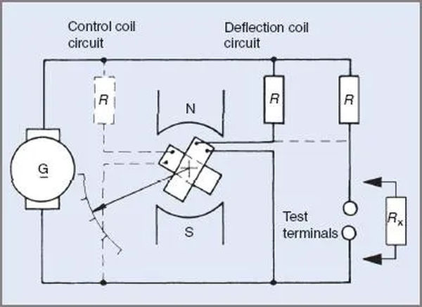
Visible connections reveal the incorporation of variable resistors. The knobs on the side of the instrument case help with this (see Figure 5). The four rotary switches used to activate the resistance box part of the bridge measuring circuit are located on the top of the device.
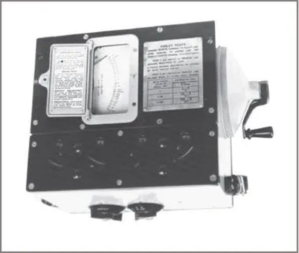
The bridge megger is a direct-reading series ohmmeter for high resistance values, making it ideal for use as an insulation tester. When using a bridge setup, the circuit needs to be balanced using the knobs. When establishing a zero or balanced point, infinity is used as the reference point. The infinity sign is directly above the pointer when it is in the bridge-balanced position.
The identification of cable faults is facilitated by a bridge megger instrument. It is possible to calculate the distance to the fault location by measuring the resistance between the cable terminations and the site of the problem. The most common circuit connection is called a “Varley loop” after the inventor of the idea.
TDR meters are more modern instruments used to find problems in power or communication cables. Common problems they detect include open and short circuits, crossed pairs, and more.
Continuity Testing
In order to check the continuity and resistance of conductors in a setup, there is yet another version of the megger circuit. The continuity tester functions like a parallel-connected ohmmeter, whereas the standard megger functions as a series ohmmeter for resistance ranges of 0-100 MΩ, 0-200 MΩ, and in some cases, 0-550 MΩ. The typical resistance range is determined by the maker. In most cases, the continuity feature of a megger is used to conduct earthing continuity tests.
Hi-Pot Testing
Insulation tests are commonly conducted at 1500 V, or up to 4500 V, in accordance with Australian and International standards. We anticipate that insulation, clearance, and creep age distances will be sufficient to prevent 1 mA from flowing even at such high voltages.
Care in the Use of Meggers
Care must be taken when using a 500 V megger to avoid the risk of receiving an electric shock. It’s possible to get an unpleasant electric shock from touching the test leads by accident. The same goes for any other technicians who come into contact with the same conductors during testing.
High-voltage testing is commonly performed on underground cables. In most cases, 3000 V meggers are used for this. In addition to the risk of electric shock from the instrument itself, the capacitance effects of the cable present a unique and potentially disastrous hazard. This is especially true for underground cables that are protected from the elements by an outer sheath of metal, such as armored or metal-sheathed cables, or for MIMS cables.
An electric charge can be stored on the cable due to the capacitance created by the method of construction. Usually, the charge is located between the cable’s conductor and its protective metal sheath, and it is generated by the megger’s direct current (DC).
Microfarads per unit length are commonly used because the actual capacitance varies greatly from cable to cable. The capacitance of a typical cable is about 0.2 μF/300 m. Capacitances can vary widely between different individuals.
This capacitance stores roughly 9 J of energy at 3000 V. Electric shock from this amount of charge at this voltage is sufficient to temporarily disable a technician. There are times when you should see a doctor.
There are often many kilometers of underground cable on an airport, making the potential for an electric shock very high. A relatively short length of underground cable would still have enough energy at a voltage that can kill someone.
For this reason, discharging the cable after testing is highly recommended. Most commonly, electricians will use a screwdriver to create a short circuit between the sheath and the conductor. Although this may be beneficial, it should be done cautiously because of the potential for additional risks.
If a megger is to be used on a capacitive installation, the operator must first charge the installation to the megger’s voltage. This is typically accomplished by running tests on a single conductor for an extended period of time. When the meter reading settles to a single value, this is usually the case.
A low reading on the megger may indicate a path to earth, for instance when testing the resistance of a single conductor in a buried cable to the cable’s sheath. In most cases, the megger reading will increase to a much higher and more acceptable level as the test progresses.
Fault Loop Impedance Testers
Current industry standards for electrical workers entail that they inspect the installation’s fault loop. From the installation’s main earth, the fault loop follows the path back to the supply point where the main neutral is grounded, completing the circuit.
The purpose of fault loop impedance testers is to provide some kind of indication of the impedance along that path.
The device being tested may perform multiple tasks at once, including those of a megger, continuity tester, and residual current device tester.
Loop testing involves connecting a known resistor across one phase of the setup and taking readings at both normal and faulted conditions. The instrument then converts this information into an ohms impedance reading for the circuit’s earth return, which connects back to the power source.
An effective earth return is typically required of safety and residual current devices. Particularly with more recent electronic devices, loop impedance testing can trip the device and possibly damage it. An interruption in supply service can range from being a minor inconvenience in a household to a potentially catastrophic safety issue in a commercial or industrial setting.
A typical fault loop impedance tester is depicted in Figure 6. It’s worth noting that this tool can also be used to check for potential fault levels in a given setup. Each tester has two different types of leads: one with a male plug for checking wall outlets, and another with alligator clamps for checking more complex electrical systems.
