Let’s take a look at the induction generator’s operating principle and see how it functions.
If the rotor of a three-phase Induction motor is coupled to the prime mover and the prime mover is capable of driving the induction machine rotor at a speed greater than the synchronous speed, then energy will be returned to the AC Mains. The device can then function as an Induction generator.
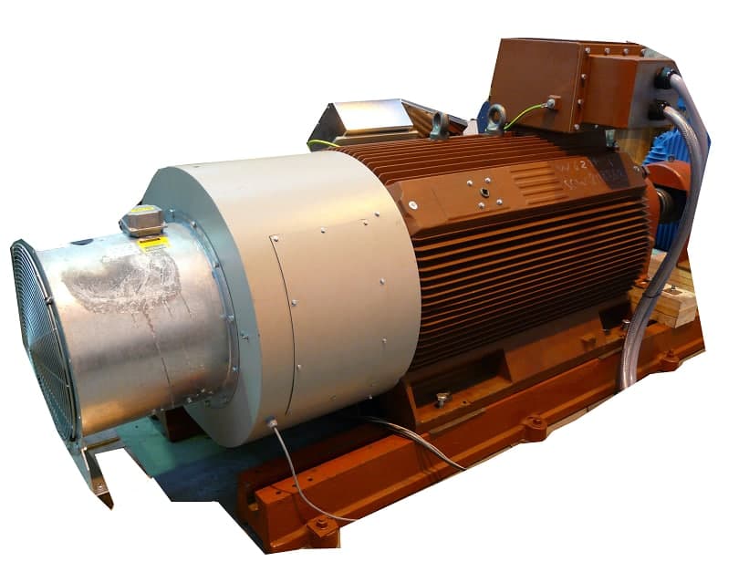
Since the prime mover spins the rotor at a rate greater than the synchronous speed, the slip value for induction generators is negative. Another name for an induction generator is an asynchronous generator. Given that rotor speed deviates from synchronous frequency.
Types of Induction Generators:
1. Grid connected Induction generator
Connecting an induction generator to the grid requires reactive power, which is provided by the system.
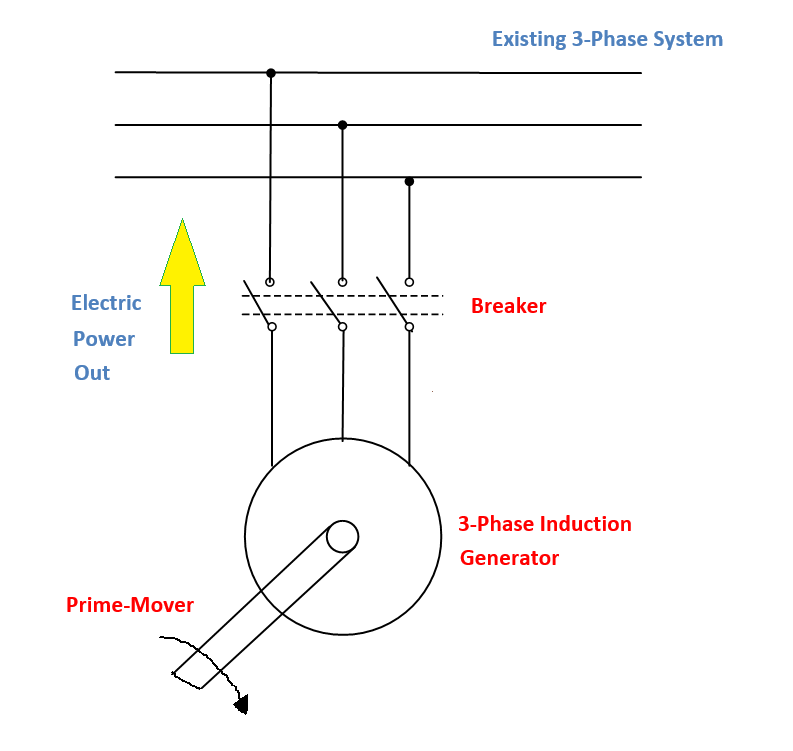
Induction motors get their excitation from the utility grid through a connection at the stator. Aluminum or copper bars form the squirrel cage-style rotor. The slip becomes negative and the induction generator begins supplying power to the supply mains if the shaft is accelerated to a speed greater than synchronous speed.
2. Isolated Self-Excited Induction generator
A bank of capacitors with a delta connection is wired across the induction machine’s terminals, as shown in the diagram below.
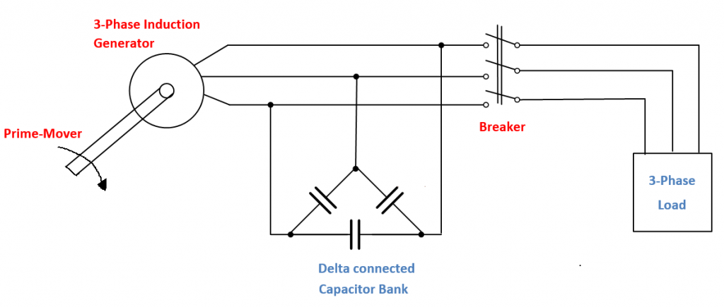
The excitation current for the generator function is supplied by the capacitors connected in a Delta configuration. Because of these capacitors, the induction generator can generate voltage by storing reactive power. Reactive power is also provided by these capacitors to the load.
Rotor residual magnetism causes a small amount of emf to be induced in the stator when the prime mover rotates the rotor. This induced emf has a frequency that varies with the rotor’s rotational rate. In this configuration, the device functions as a self-exciting induction generator.
A windmill could be the driving force.
3. Doubly fed Induction generator-DFIG
DFIGs are used in wind turbines as a variable speed generator for their many benefits.
Methods of Induction Generator Operation
The graph below depicts the torque-speed characteristic curve of an induction motor. When the rotor’s speed is below synchronous speed, the machine functions as a motor, and when it’s above synchronous speed, it operates as a generator.
As shown in the figure, the generator can only operate within a certain torque range, as defined by the maximum value of torque corresponding to a slip of OP.
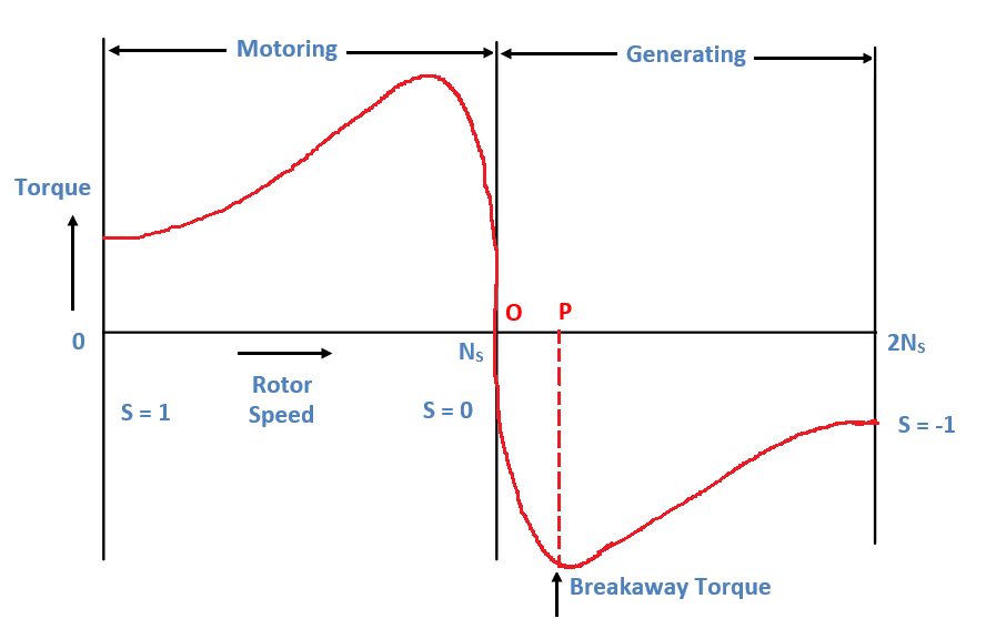
Above synchronous speed, operating an induction generator becomes impractical. It’s important to keep the generator’s rpm below the breakaway torque. When the speed exceeds the breakaway torque, the real power quickly drops to a negligible level.
The following safeguards must be in place for an induction generator:
- Over speed protection, typically provided by governors or speed limit switches, is necessary to keep the generator from reaching the pushover point and wasting energy before it can generate real power.
- Stopping the motor from running requires relays that cut power in the opposite direction. When the induction generator is being used as a motor, these relays will cut off the power to it.
- Over excitation and the generation of uncontrolled high voltages can be avoided by disconnecting the power factor capacitors from the generator using a dedicated breaker when the generator is operating at under or over speed.
How an Induction Generator with Two Power Sources Works
Induction generators that were “doubly fed” received alternating currents in both their stator and rotor windings. The generator uses the wind power captured by the turbine to produce electricity, which is then transferred to the grid via the stator and rotor windings.
The primary benefit of DFIG is that the amplitude and frequency of their output voltages can be kept constant regardless of the speed of the wind turbine rotor. Therefore, DFIG can be hardwired into the AC power grid while simultaneously maintaining synchronization.
Components of a Double-Feed Induction Generator
1. Three-phase Wound rotor Induction Machine
Using a three-phase wound rotor, the Doubly fed Induction generator can produce power in two directions. Two back-to-back converters link the wind turbines’ rotor windings together, while a power transformer links the turbines’ stator windings directly to the grid.
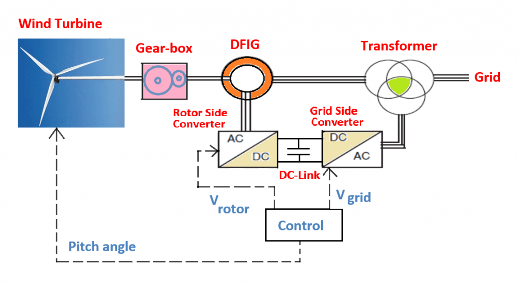
2. Back to Back converters [AC/DC/AC Converter]
An RSC (Rotor Side Converter) and a GSC (Grid Side Converter) are the two converters used in this configuration. The reactive power injected by these converters is used to regulate the system’s terminal voltage and power factor.
The Rotor Side Converter-RSC: [AC/DC]
The rotor side converter is linked to the generator slip rings and communicates with the grid side converter via a DC link.
The RSC regulates the power factor at the stator terminals and the generator’s torque/speed in response to commands about the pitch angle and voltage. The rotor currents are managed by RSC. The slip, and thus the speed of the machine, can be modulated by adjusting the rotor currents and their frequency.
Grid Side Converter-GSC: [DC/AC]
Maintains a constant DC-link voltage and regulates reactive power or terminal voltage in response to an input voltage command.
3. Capacitor in the DC Link
Connecting the two converters is a DC-link capacitor. In order to maintain the DC-voltage, link’s it functions as a DC voltage source.
Synchronous vs. Induction Generators
When comparing Synchronous and Induction Generators, there are a few key distinctions.
- Induction generators that are either hardwired into the power grid or used to power small, intermittently available hydraulic turbines used to generate power from water, as well as load driving hoists used to generate braking torque, are examples of such devices.
- When renewable energy sources, such as windmill generators, are used to produce electricity in remote areas, self-excited induction generators are used. Stand-alone power supply units, such as induction generators, are frequently used to provide electricity to loads in far-flung locations.
- Dual-feed induction generators are common in wind farms. By ensuring the network continues to run smoothly and with higher power quality, DFIGs are beneficial.
- Comparing Synchronous and Induction Generators
- The DC excitation of an induction generator is unnecessary.
- When hooked up to a three-phase power source, an induction generator that is also grid-connected will produce electricity.
- Parallel capacitors are used to supply reactive power for self-excited induction generators that are not connected to the grid.
- Since an induction generator only produces power when the slip is negative, synchronization is unnecessary.
- Lower resistance was intentionally designed into the rotors of induction generators to cut down on losses and slip.
- There is no need for a voltage regulator because the output voltage and frequency are unaffected by changes in speed. The power grid regulates the voltage and frequency of electrical currents.
- The design is straightforward, especially when put next to a synchronous motor. It calls for less ancillary machinery. To eliminate the need for collector rings, diodes, and brushes.
- The cost to maintain it is lower.
- The high energy density allows for a compact design in terms of kilowatt output.
- Large power swings do not cause the generator to become desynchronized from the network as they would with a synchronous generator.