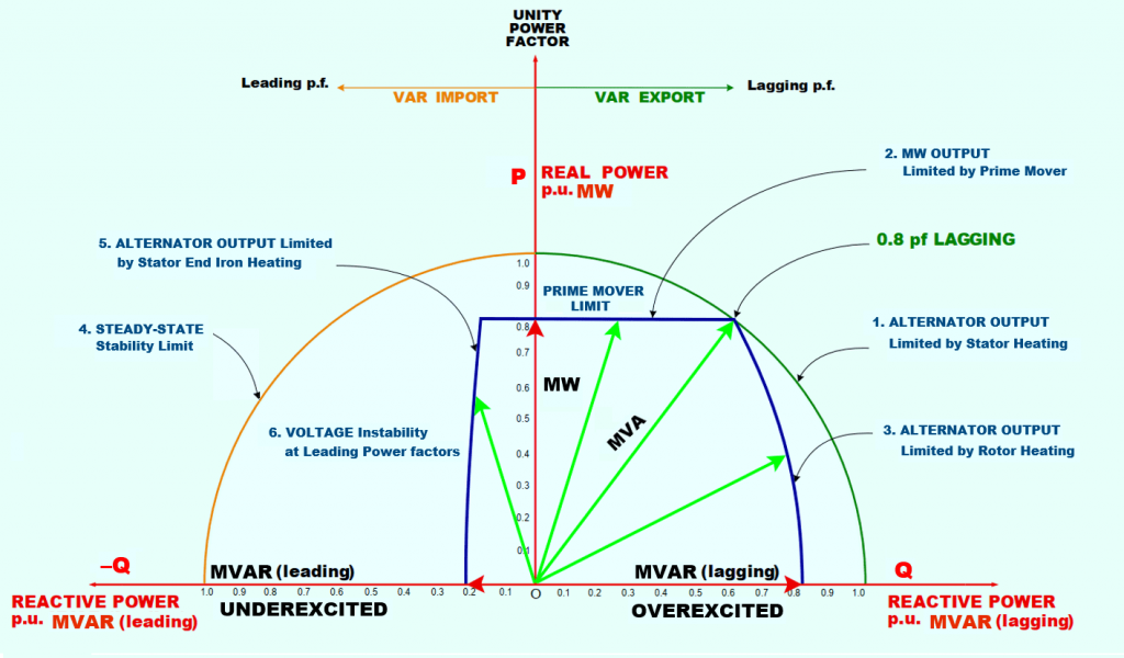
The generator capability curve specifies the allowed range of generator operating points. Active power (MW), reactive power (MVAr), and apparent power all contribute to the generator load capability curve and the generator’s operational capability (MVA).
The PQ axis is used to plot the capability curve. With P denoting MW and Q denoting MVAr.
Data extracted from the Power Generation Capability Curve:
- Maximum Generation Limit
- Find out how far you can push the generator before it loses its steady-state stability.
- Restrictions placed on the generator’s components.
- For the purpose of making the reactive power component of the active power pricing mechanism more transparent and efficient.
- With knowledge of the generator’s safe operating limits, you can adjust the protection system’s settings.
- In cases of under-excitation, this is the absolute minimum that can be said to apply.
Features of the Generator:
- Rated maximum MVA for synchronous generators at nominal voltage and power factor (usually 0.85 or 0.9 lagging).
- It is the prime mover that sets the upper bound on the active power output.
- Armature current limit, field current limit, and end region heating limit are the three factors that cap the continuous reactive power output capability.
Within the area delimited by the circle in the diagram below, it is impossible to run a synchronous machine at full capacity.

Generator Limitations:
The operation of the generator is restricted in six main ways.
- Stator winding heating limit.
- MW limit.
- Rotor heating limit.
- Steady-state Stability limit.
- Stator core end heating limit.
- VOLTAGE Instability at Leading Power factors.
1. Stator Winding Heating Limit:
The conductors in the generator’s stator are reaching their temperature limit. Because of I2R heating in the stator conductors, we are at our utmost capacity.
By adjusting the generator’s power factor to be closer to UPF, the stator current can be reduced, bringing generator stator conductor temperatures safely close to their design limits.
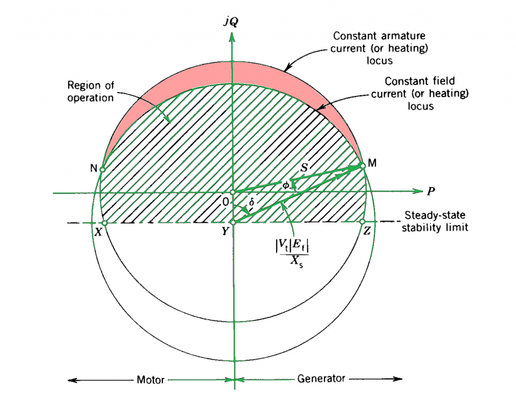
The maximum current that can be carried by the armature without exceeding the heating limitations is one of the limitations of generator rating. The armature current limit, depicted as a circle in Figure, has a center at the P-Q plane’s origin and a radius equal to the MVA rating.

The region of operation where armature heating does not exceed the specified limit is defined by the circle with center at the origin O and radius S= Vt*Ia.
2. MW Limit:
There is a cap on MW production due to the interaction between turbine output and stator conductor heating. Because of the limitations of the prime mover, the generator’s actual power output is typically well within the apparent power rating. In most cases, the active power limit imposed by the generator stator current is lower than the maximum capability of the prime mover.
3. Rotor heating limit
The field current imposes a second limit on the operation of the generator due to the heat generated by the rotor currents due to I square R losses. This constraint prevents rotor conductors from delivering more power to the rotor. The machine’s performance suffers when the limit is exceeded due to the excitement.
4. Steady-state Stability limit
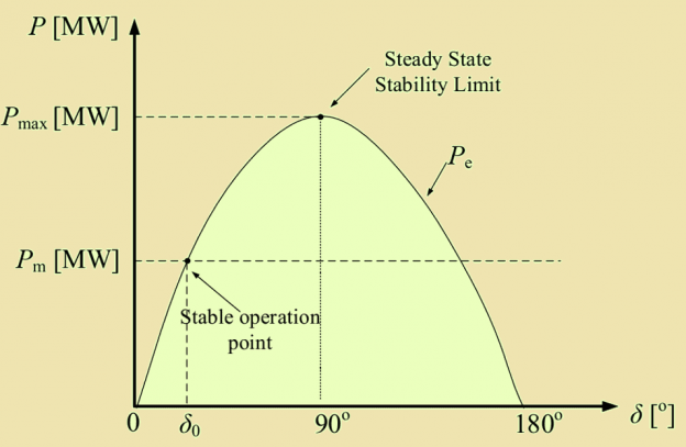
This limit is known as the steady-state stability limit, and it represents the maximum power that can be transferred without causing instability in a system where the load is gradually increased over time.
The rotor’s excitation and, by extension, the flux it generates, is low when the power factor is leading. In turn, this results in a weak magnetic coupling between the rotor’s and stator’s rotating magnetic fields. Under these circumstances, the generator will experience a high load angle (rotor angle).
This load angle of 90 degrees represents the steady-state stability limit of the generator for the excitation being used.

If the load is increased any further, the magnetic fluxes will stretch and the load angle will increase. The magnetic coupling between the rotor and stator is broken when the rotor is in the 180 Deg position. The rotor spins faster and the generator produces only brief surges of power as the rotor’s N pole moves past the stator’s S pole when this happens. The generator has become unstable due to an effect known as “pole slipping.”
From a mechanical standpoint, the large power surges place significant stress on the generator to turbine coupling, the bearings, and the foundations. Electrically speaking, all load-carrying components will be subjected to magnetic stresses due to the resulting current surges caused by the power surges. Lightning and voltage fluctuations are both side effects of power surges.
It is important to note that the stability limit line indicates the maximum number of leading vars that can be used with the generator without risking its stability.
For maximum stability, the XYZ line represents an absolute minimum value.
5. Stator core end heating limit.
The rotor produces a large flux when the power factor of a generator is either 1 or 0. As a result, there is no excessive heating at the core ends and minimal flux leakage from the stator.

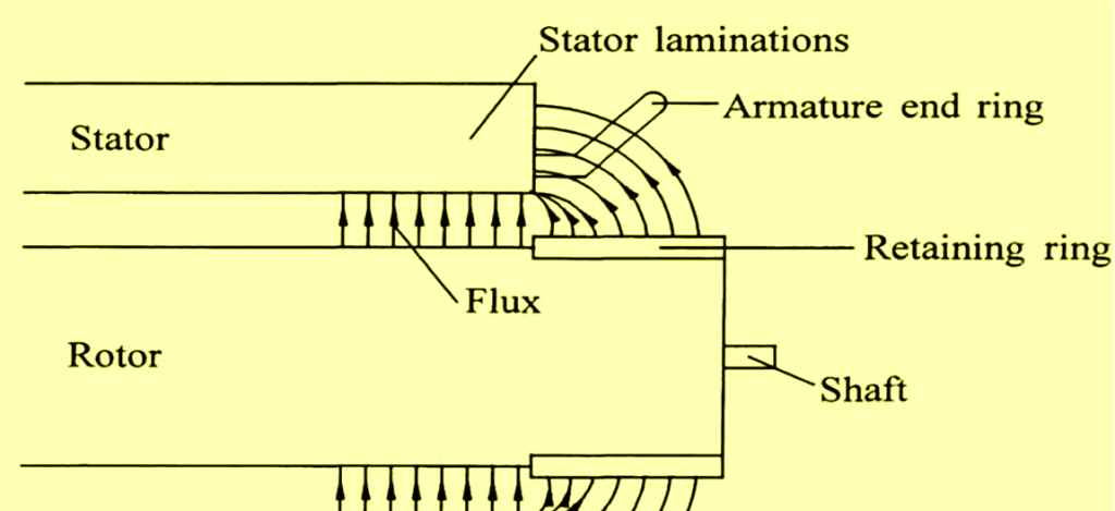
More flux escapes from the ends of the stator core and the rotor’s flux is weakened when the generator is operating at a leading power factor. This flux escapes from the stator core’s ends, travels along the face of each lamination, and induces strong eddy currents. Extra heat can be generated by these eddy currents.
6. VOLTAGE Instability at Leading Power factors.
Limiting terminal voltage output is stator iron core heating, not core end heating.
CONCLUSION:
Consequently, at the rated speed (frequency) of operation, the
- There is a cap on MW production due to the interaction between turbine output and stator conductor heating.
- Overheating of the rotor restricts Mvar output (lag).
- Stator core end heating and stability constraints set upper bounds on Mvar output (lead).
- The stator iron core’s temperature places a cap on the terminal voltage output.