An EHV transmission line is a type of electrical transmission line that can carry large amounts of power at a single location. This eliminates the need for additional conductor. EHV lines are commonly used in India to carry electricity at voltages of 220, 400, and 765 volts.
Only at voltages in the EHV/UHV range is it technically and economically feasible to transmit bulk power from generating stations to load centers. This is the case for both technical and economic reasons.
Transmission lines that carry extremely high levels of alternating current are known as EHVAC lines. Since EHV lines can transmit a lot of power over a small distance, fewer wires are needed to build the system.
Power Grid Corporation provides EHVAC transmission in India at 220kv, 400kv, and 765kv.
Pros of EHVAC Transmission
- Transmitting massive amounts of power over great distances:
Power transmission capacity

Where Vs= Sending End voltage
Vr= Receiving End Voltage
X= line reactance
δ= Load angle
- Surge Impedance Loading Increases
Surge impedance loading is commonly used to describe a line’s carrying capacity (SIL).
Surge impedance loading (SIL) is the power that a line carries when each phase is terminated by a load equal to the surge impedance of the line.
- The surge impedance of a transmission line is defined as ZC = √L/C, where L and C are the series inductance and shunt capacitance per unit length, respectively.
- A transmission line’s surge impedance loading (SIL) is defined as 3V2/ZC, where V is the line-to-neutral voltage.
- We can see that SIL changes proportionally to the square of the operating voltage, so as the voltage rises, so does SIL. Therefore, the line’s power-transfer capacity grows as the voltage rises.
The Benefits of EHVAC Transmission
- Used to transmit high power over great distances.
- Intensification of Surge Loading
- When the voltage is increased, the losses also go down.
- Reduced losses allow for more efficient transmission.
- At higher voltages, a smaller amount of conductor material is needed.
- A lower percentage of line drops aids in voltage regulation.
The Issues with EHVAC Message Transmission:
Electrostatic fields near the lines, noise, radio interference, corona losses, carrier and TV interference, high voltage gradients, heavily bundled conductors, voltage control at power frequency using shunt reactors of the switched type that inject harmonics into the system, switched capacitors, overvoltages caused by lightning and switching operations, long air gaps with weak insulating properties for switching surges, and ground-return potential differences are all threats to EHV lines.
Limitations of EHVAC Data Transmission:
1. Coronal Losses:
When electric fields exceed the air’s insulating strength close to the conductors, localized discharge processes can increase per-unit-length (p.u.l.) losses in high-voltage transmission lines.
2. Radio Interference
Whenever corona forms close to EHV lines, it causes radio interference that degrades the sound quality of AM radio transmissions. Interference from radio waves typically occurs between 0.01 MHz and 30 MHz, at higher frequencies.
Carrier Communication and Signaling are disrupted from 30 kHz to 500 kHz due to corona on conductors.
Disturbed Auditory Environment
The audible spectrum, from 20 hertz to 20 kilohertz, is where corona discharge is audibly emitted. The resulting buzzing noise is a result of the total amount of energy being wasted as a result of the noise.
Luminosity
As the corona’s emitted fields enter the visible spectrum from 380 nm to 780 nm, a violet luminosity is created.
3. The Need for Better Insulation Has Grown:
The magnitude of potential voltage surges, whether from within the system (during switching operations) or from without, determines the necessary level of insulation (lightning etc.)
Ground wire and fast-acting, auto-closing circuit breakers are common methods for safeguarding the lines against lightning and other potential hazards.
This insulation is designed for a maximum switching surge overvoltage to ground of 2.5 p.u. In addition, there is sufficient safeguarding against atmospheric overvoltages.
4. Demand for Robust Underpinnings
Due to factors such as bundled conductors, large air and ground clearances, and the pressures of the wind during storms and cyclones, the towers supporting EHV transmission lines experience significant mechanical loading.
Primary Elements of HVAC-R Power Plants:
1. Conductors in Bundle
The configuration of so-called “bundle conductors” is formed if two or more cylindrical conductors would be at the same potential with reference to predominantly earth potential far away from the parallel conductors; this system is widely used in E.H.V transmission lines.
Conductor Bundling:
This is because the single conductors interact with one another, lowering the maximum field intensity at the conductors compared to a single cylindrical conductor and allowing the corona inception voltage to be significantly increased.
Bundled conductors’ characteristics:
A circle with a radius R has a uniform distribution of a bundle’s sub-conductors across its surface.

The above diagram illustrates a few common ways in which bundles of Conductors are configured in E.H.V lines.
Distance Between Bundles (Bundle Spacing) = Distance Between Neighboring Subconductors
Bundle Radius R=Pitch Circle Radius where the Sub-Conductors are Located.
2. Ground Return :
When a transmission line is operating in an unbalanced configuration, ground-return currents do not circulate. Yet there are numerous cases in practice where ground currents significantly impact system performance.
The following are examples of some of these:
- Current direction during ground-based short circuits. Only L-G and L-L-G faults (two lines to the ground) are excluded.
- Lightning and other forms of transient discharge;
- Wave motion in conducting media;
- Radio noise research.
3. Shunt Capacitors
Reactive power is injected and the voltage at the receiver is regulated using shunt compensation with capacitive VARs. With shunt capacitors installed across an inductive load, only a fraction of the reactive VARs needed by the load need to be transmitted over the line, keeping the voltage across the load within acceptable parameters.
4. Condensers in series
To counteract the effect of the series inductive reactance of the line, capacitors are connected in series with the line at strategic points. As a result, the inductive reactance between the load and the power source is diminished by the use of these capacitors.
5. Shunt Reactors
Reactive power is created along long transmission lines due to capacitance between the lines and the ground. Reactive power is wasted and must be balanced to prevent unnecessary energy loss.
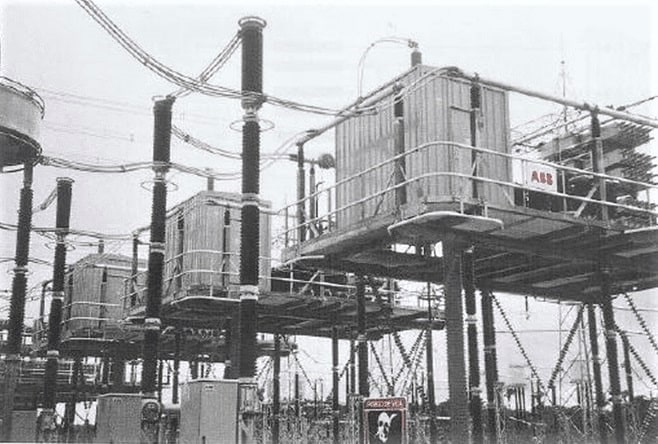
For reactive power compensation, the most common device is a shunt reactor, which acts as an absorber. To regulate the voltage across the loads, shunt reactors are placed across capacitive loads or lightly loaded lines to soak up excess leading VARs.
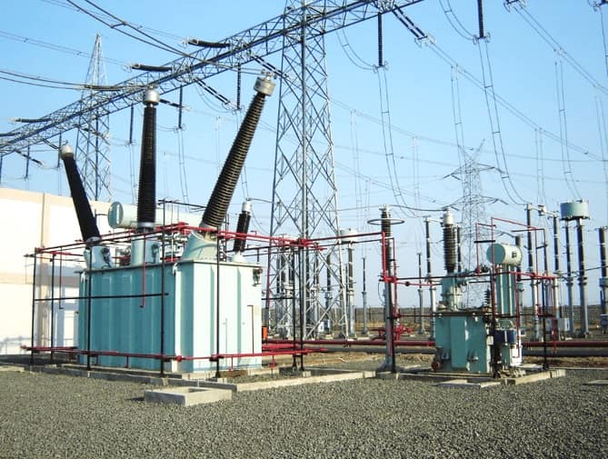
The shunt reactor may be hardwired into the power grid or connected to the third winding of a three-phase transformer. The shunt reactor could be hardwired in or operated by a toggle switch. The reactor’s rating can be adjusted to better regulate the amount of reactive power it consumes.
Since loads tend to fluctuate over time, variable shunt reactors let the compensation be fine-tuned on the fly. They eliminate potentially dangerous voltage steps by rendering the switching in and out of fixed-rating reactors superfluous.
The Ferranti Effect Is Negated by Shunt Reactors
The transmission line voltage rises at low loads. When the load on the generator is suddenly eliminated, there is also a rise in the voltage at the sending end of the line.
The shunt reactor is placed at the load end to prevent an excessive voltage increase caused by the Ferranti effect.
We also know that the voltage at the receiving end of the line is greater than the voltage at the sending end of the line due to the capacitive load on the line. This rise is roughly 13 percent at 500 kilometers, 100 percent at 960 kilometers, and 1.5 percent at 160 kilometers.
The voltage rise is mitigated, the voltage is maintained within acceptable parameters, and the system’s voltage stability is enhanced by the use of a shunt reactor.
6. Synchronous Condenser
Overexcitation of a synchronous machine results in the production of reactive power and the shunt capacitor behavior. The synchronous condenser operates with no load. Changing the DC Excitation is a simple and continuous way to regulate the reactive power.
7. FACTS Devices
Power electronic devices are used in conjunction with flexible AC transmission systems to improve system controllability.
The most common uses for FACTS technology are
- An increase in one’s ability to direct energy in the desired direction (… Deregulation)
- Safety in line loading (not overloading)
- More balanced power distribution amongst systems
- Equalization of reactive power
- Avoiding a Domino Effect
- Reducing Vibrations in the Power Grid
- When and how often it is open for business.
Series Compensation
It does this by having capacitors connected in series with the line at appropriate locations, which works directly against the effect that the line has of having a series inductive reactance.
Advantages:
- Improvements to the Transmission Capacity
- Stability enhancement of the system
- Splitting the load between parallel circuits
- Improvements in voltage regulation
- Acronym for “Thyristor Controlled Series Capacitor”
Thyristor Controlled Series Capacitor: TCSC
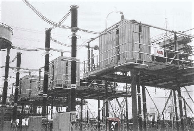
Through TCSC, compensation levels can be adjusted as needed. A Thyristor Controlled Reactor and a Series Capacitor are the two main components of a TCSC (TCR).
TCSC’s level of compensation can be fine-tuned by adjusting the firing angle of the thyristor (on/off switch).
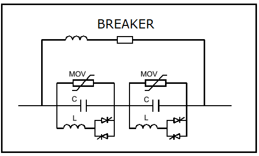
The above diagram depicts the TCSC mixture with the MOV-Metal Oxide Varistor.
Compensation for Shunt:
Capacitive reactor shunt compensators (Static VAR and STATCOM) are used to
- Management of Grid Voltage
- avoiding dangerous voltage spikes in the event of load loss
- rectifying voltage drops caused by faults
- Suppressing active power oscillations
- In order to improve voltage regulation,
- Harmonic filtering, flicker mitigation, and load balancing are all ways in which power quality can be enhanced.
Varieties of Shunt Compensation:
- Equalizer for static VAR:
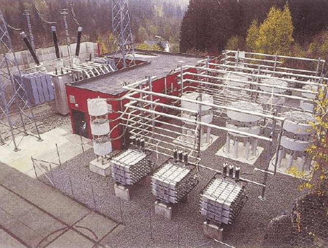
The following devices make up a Thyristor-based SVC system:
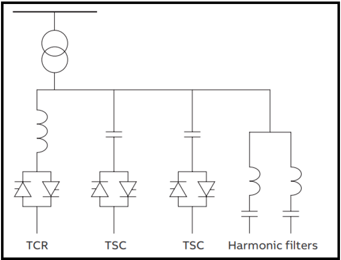
- Nuclear reactor with thyristor control (TCR)
- Capacitors with thyristor switches (TSC)
- Reactor with Thyristor-Switched Switches (TSR)
- Modulation Filters for Harmonics
- Static Synchronous Compensator, or STATCOM for short
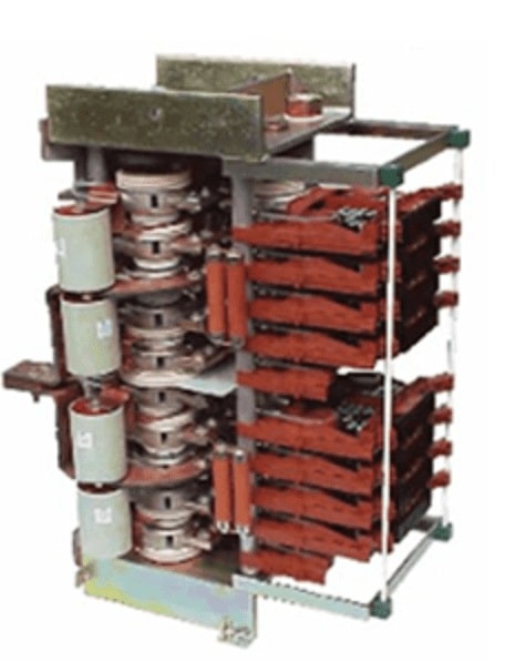
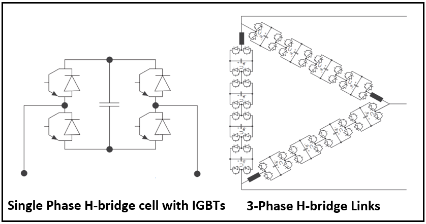
STATCOM uses high-power insulated-gate bipolar transistors (IGBTs) and insulated-gate commutated thyristors (IGCTs). These components are used to create Voltage Source converters that operate at multiple levels in a chain. As can be seen in the diagram below, VSC is created by connecting H-Bride modules in series.
