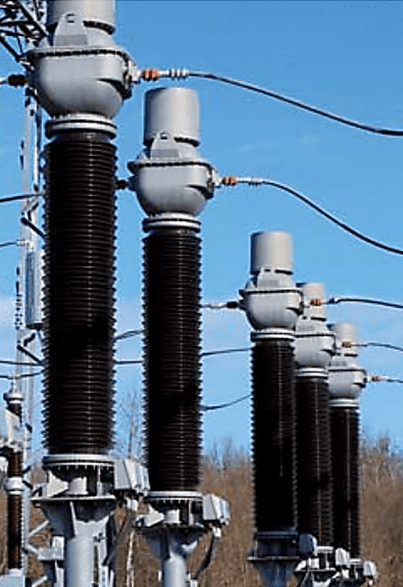
A combined instrument transformer is used to step down the voltage and current to a defined value. This type of transformer can be utilized in various applications such as power monitoring and protection. It can also insulate equipment from high-system-volt levels.
A current transformer and an inductive voltage transformer are housed in the same casing in a combined current and voltage transformer, also known as a combined instrument transformer (CIT).
The high voltage system’s metering, protection, and control are all made possible by combined instrument transformers, which take in transmission line voltages and currents (up to 145kV and 5000 A, respectively) and transform them into more manageable, low values (down to 110v and 1A, for example).

These are typically employed in situations where precise and dependable voltage and current transformation is crucial.
benefits of a combined instrument transformer
Total substation ownership costs can be reduced by consolidating CT and VT modules into a single enclosure because of:
- Transformer bays with fewer devices.
- Less primary connections and fewer supports means less material is needed, which means lower costs.
- One unit can be transported for the price of two, saving you money.
- Since there is only one footprint, less room is required.
- Expenses for infrastructure improvements are reduced.
- One fewer unit to set up means less work for the installer.
Voltage-Current Transformer Combo
In substations where separate Transformers would be difficult to install due to limited space or high installation costs, combined transformers are a viable alternative.
- This current and voltage meter has a very high accuracy class, making it ideally suited for installation at metering points. Check and indication meters, as well as revenue meters, use these.
- Appropriate for depleting high-voltage circuits and capacitor arrays.
- The frequency response is superb, making it an ideal tool for gauging harmonics and keeping an eye on power quality.
Building a combined current-voltage transformer
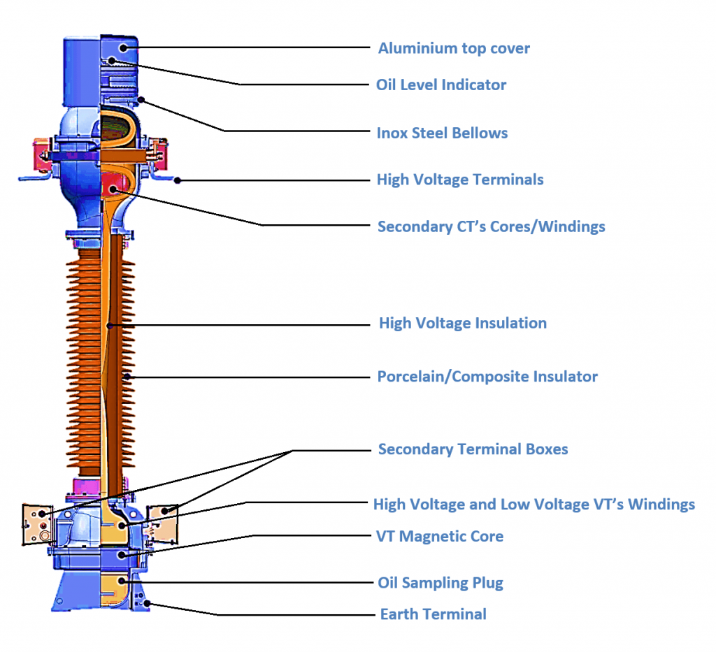
As was previously mentioned, a current-input transformer (CIT) houses both the current transformer (CT) and the voltage transformer. CIT’s unique design can be seen in the placement of the voltage transformer’s active component at the bottom of the porcelain housing and the current transformer’s location at the top.
In terms of dielectric, you can choose between oil and SF6 for your combined instrument transformer.
Here, we’ll think about a combined instrument transformer with oil insulation.

- Each transformer has high voltage (HV) terminals at the top and low voltage (LV) terminals at the bottom. The VT bushing carries high voltage cables connected to the high voltage transmission line, and the center pipe of the CT bushing carries a secondary terminal (low potential) connected to the cable box.
- The heart and soul of your CT machine, the core and windings, are up there. The windings and cores of a VT can be found at the base of the machine.
- Increased short circuit current and reduced voltage drop across the primary winding are both benefits of the bar-type primary conductor.
- Combined instrument transformers with oil insulation are used to separate high and low voltage measuring instruments from each other safely and reliably.
- Walls lined with oil paper. Mineral oil is of the highest quality and is PCB-free.
- The use of a porcelain or silicone composite insulator for exterior use.
- Aluminum or stainless steel is used for the exterior components.
- The oil-paper insulation is safeguarded from environmental influences by the hermetically sealed housing. The oil volume can be adjusted to maintain a constant internal pressure of 1 atmosphere above ambient, thanks to a bellows made of suitable lnox steel that is located at the top of the Combined Transformer.
- An oil level mechanical system is visible through the bellows cover window.