A capacitor voltage transformer is a type of electronic device that converts high-speed transmission class voltage into useful and measurable values. It can be used for various applications such as protection and control of high-voltage systems.
A combination of CCVT (Capacitor Coupled Voltage Transformer) and CVT (Capacitor Voltage Transformer) capacitors can be used to coupling carrier signals from high-frequency power lines.
Transmission power systems have made extensive use of capacitive voltage transformers (CVTs) for high-voltage and ultra-high-voltage applications.
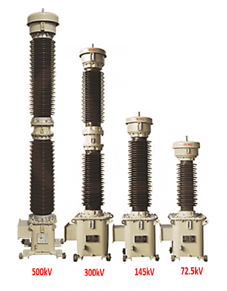
Transmission systems make use of capacitive voltage voltage transformers and coupling capacitive voltage transformers with ratings from 72kV to 1200kV.

A CVT’s primary function is to measure voltage and transmit that information to other devices such as meters, relays, and controllers.
Let’s take a look at the various voltage transformers available before we dive into the meat of the discussion.
Voltage transformers
Measure and safeguard electrical systems with voltage transformers, also known as potential transformers. Protecting against voltage, direction, and physical separation all necessitate the use of voltage transformers.
Depending on the rated voltage and the application, the primary side of the voltage transformer is wired directly into the power circuit between phase and ground.
Voltage transformers come in three varieties:
1. Electric Magnetic Voltage Transformers
CVT Coupling, or Capacitive Voltage Transformer “Capacitor Voltage Transformer” (or “CCVT” for short)
Where the primary and secondary windings are typically found on a magnetic core. Secondary voltage is a proportionally lower voltage that can be used for testing or shielding.
2. A capacitor voltage transformer, or CVT
The Capacitor-Variable-Transformer (CVT) is a hybrid device that combines the features of a voltage divider with those of an EVT. In which a series of capacitors receives the mains current.
The Electromagnetic Voltage Transformer receives the reading of the voltage across one of the capacitors. The EMVT secondary is typically used for testing or security purposes.
3. Coupling Capacitor Voltage Transformer, abbreviated as CCVT
A coupling capacitor and continuously variable transmission (CCVT). One uses a coupling capacitor to shield a carrier current and make contact.
Electricity Transmission Over Power Lines Modern PLCC gear is utilized in the realms of carrier-level communication, protection, and control.
Construction of Capacitive Voltage Transformer: CVT
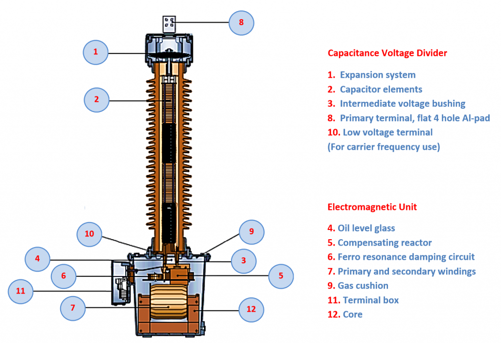
The three main parts of a CVT (capacitive voltage transformer) allow for its construction.
Capacitance Voltage Divider- A capacitor voltage divider is a series of capacitors that are used to regulate voltage. Depending on the input voltage, it may consist of a single or multiple stages.
Electromagnetic Unit – has a compensating reactor and a step-down transformer.
Ferro Resonant Damping Circuit– It consists of an Iron core reactor and a resistor
1. Capacitance Voltage Divider:
Capacitor sections are groups of capacitor elements wired in series and housed in individually sealed porcelain canisters. Each capacitor element’s dielectric is a layer of high-quality polypropylene film/paper saturated with a highly processed synthetic fluid. The synthetic fluid in the capacitors can expand and contract with changes in ambient operating temperature thanks to the stainless steel bellows installed in each capacitor section.
Line-to-ground voltage is applied to the capacitor, and a capacitance voltage divider steps down the voltage to an intermediate range, usually between 5 and 20 kilovolts.

2. The electromagnetic unit:
An electromagnetic circuit in the cast aluminum base box is powered by a tap voltage taken from the capacitor’s lowest section (typically between 5 and 12 kilovolts).
The intermediate transformer, whose secondary windings will be tapped multiple times for safety and metering, can be found in the lowest enclosure.
In order to counteract the voltage divider’s capacitive reactance, a compensating reactor is connected in series with the capacitors. Dried mineral oil is used to fill the base box, which prevents environmental damage to the internal components.
All of the windings of the secondary of the capacitor voltage transformer are fused with HRC cartridge fuses.
3. Ferro Resonant Damping Circuit:
A Ferro resonance damping circuit is installed in the bottom case. Resonant circuits and RC time constants result from adding capacitance in series and shunt to the power system’s inherent inductance. Depending on the nature of the network disturbance, this circuit may be excited into a resonant state that will eventually saturate the transformer’s iron core. This phenomenon can cause the electro-magnetic unit to overheat or cause the insulation to fail.
The performance of numerical relays is negatively impacted by transients generated by resonance.
Therefore, a damping circuit is necessary for CVT to get rid of this resonance.
One of the secondary windings is connected in parallel with the damping circuit. The iron core reactor and series resistor make up the damping circuit. With the iron core of the damping reactor not being saturated, a high impedance is produced, and almost no current flows through this circuit under normal operating conditions.

A Coupling Capacitor Voltage Transformer (CCVT) Is Being Built.
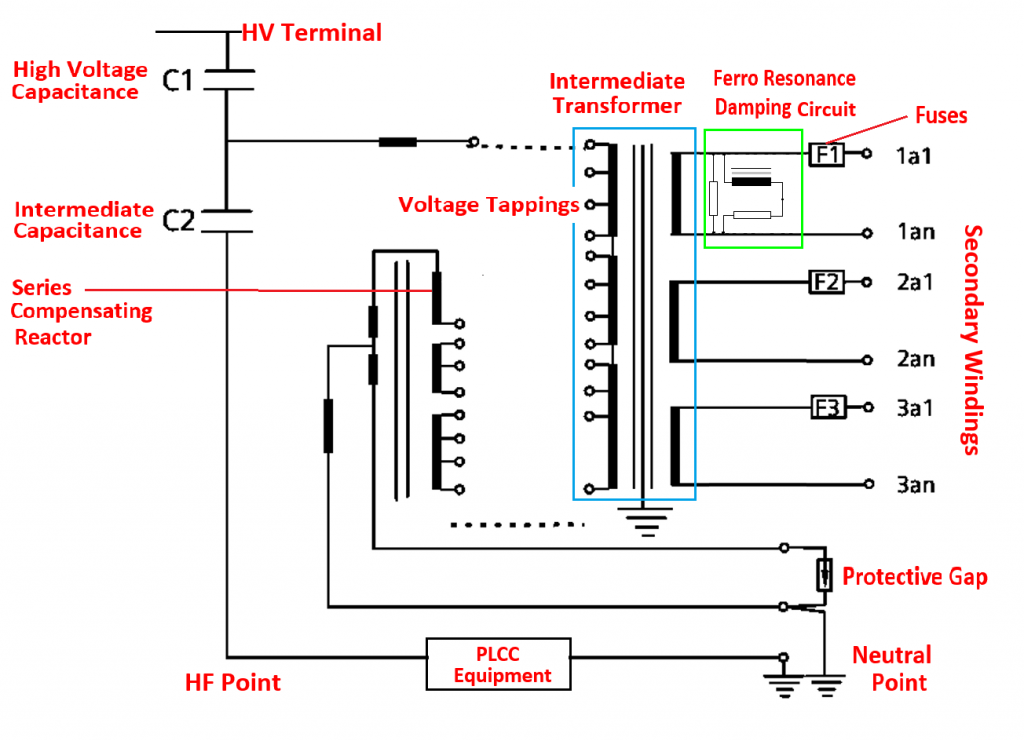
The above diagram depicts a coupling capacitor voltage transformer (CCVT), which is very similar to a conventional CVT except that it also includes a carrier coupling unit, also known as PLCC apparatus.
In order to use power line carrier technology for telecommunications, CCVTs are coupled to the power system. The 40 kHz to 500 kHz carrier frequency range is optimized for CCVTs.
In most cases, CVT will have an HF terminal built in for use with PLCC cables. When not in use for PLCC, the HF terminal should be grounded.
Power Line Carrier Current (PLCC) equipment and voltage transformers are combined into one in CCVT transformers.